The Golden Age of Radio Shack was probably sometime in the mid-1970s, a time when you could just pop into the local store and pay 49 cents for the resistors you needed to complete a project. Radio Shack was the place to go for everything from hi-fi systems to CB radios, and for many of us, being inside one was very much a kid in a candy store scenario.
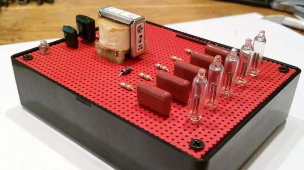
That’s not to say that Radio Shack was perfect, but one thing it did very well was the education and grooming of the next generation of electronics hobbyists, primarily through their “Science Fair” brand. Some of us will recall the P-Box kits from that line, complete projects with all the parts and instructions in a plastic box with a perfboard top. These kits were endlessly entertaining and educational, and now [NetZener] has recreated the classic neon “Goofy Light” P-Box project.
As it was back in the day, the Goofy Light is almost entirely useless except for learning about DC-DC converters, multivibrators, RC timing circuits, and the weird world of negative resistance. But by using the original Science Fair instructions, compiling a BOM that can be filled from Mouser or Digikey, and making up a reasonable facsimile of the original P-Box chassis, [NetZener] has done a service to anyone looking for a little dose of nostalgia.
It would be interesting if someone brought back the P-Box experience as a commercial venture, offering a range of kits with circuits like the originals. If that happens, maybe some of the offerings will be based on that other classic from Radio Shack’s heyday.
Continue reading “Relive Radio Shack’s Glory Days By Getting Goofy”
 His design is based around a