Measuring Tiny Current With High Resolution

measuring-microamps-at-3MHz

[Paul] knew that he could get an oscilloscope that would measure the microamp signals with the kind of resolution he was after, but it would cost him a bundle. But he has some idea of how that high-end equipment does things, and so he just built this circuit to feed precision data to his own bench equipment.

He’s trying to visualize what’s going on with the current draw of a microcontroller at various points in its operation. He figures 5 mA at 2.5 mV is in the ballpark of what he’s probing. Measurements this small have problems with noise. The solution is the chip on the green breakout board. It’s not exactly priced to move, costing about $20 in single quantity. But when paired with a quality power supply it gets the job done. The AD8428 is an ultra-low-noise amplifier which has way more than the accuracy he needs and outputs a bandwidth of 3.5 MHz. Now the cost seems worth it.

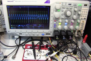
The oscilloscope screenshot in [Paul’s] post is really impressive. Using two 1 Ohm resistors in parallel on the microcontroller’s power line he’s able to monitor the chip in slow startup mode. It begins at 120 microamps and the graph captures the point at which the oscillator starts running and when the system clock is connected to it.

Hackaday Links: Sunday, July 21st, 2013

hackaday-links-chain

Adafruit tears down a set of brainwave cat ears. They’re made by Necomimi and use your brain waves to adjust a pair of plush cat ears on the headgear.

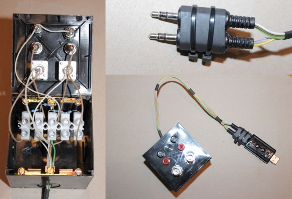
If your desktop computer is sitting on the floor you may have damaged USB dongles by hitting them with your knees. [Megacier] prevents this from happening again by building a flexible dongle link.

Can anyone help [Brian Benchoff] find a datasheet for this International Rectifier 92-O350 so he can fix up his old VT100 terminal?

Here’s a quick example of how to graph data from a Raspberry Pi on the sen.se cloud service.

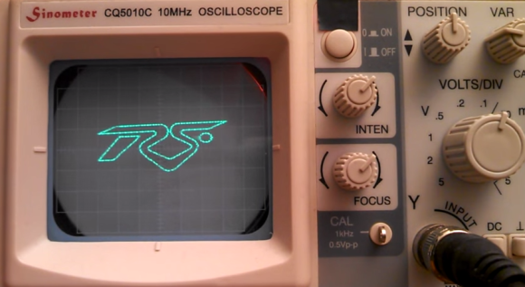
Have some extra fun with your oscilloscope by displaying any image. This set of conversions starts with a picture and ends with an audio file that will draw it on the scope’s screen.

You’ve probably already heard that the Sikorsky Prize for human powered helicopter has been claimed. If you didn’t see any footage of the flight now’s your chance. [Thanks Adam]

Arduino Oscilloscope At Five Megasamples Per Second

There’s no substitute for a proper oscilloscope on your electronics bench. But unfortunately we still don’t have one of our own. But we’ve got an Arduino board and paired with another IC it can sample an astonishing 5 million cycles per second.

[Bob Davis] has been working on an Arduino based oscillscope for a while now. He keep squeezing more and more performance out of it. A previous version hit 3 megasamples using an AD775 chip. When he added a FIFO buffer chip he was able to squeeze 10-25 megasamples out of it… wow! Unfortunately the output tended to be glitchy.

This version gets rid of the AD775 in favor of a CA3306. Both are analog-to-digital converters but the new circuit is less complex and more reliable. It uses just three capacitors and an external clock to support the IC. Take a look at the video below to see how it performs. He’s outputting a graph of the samples on a small LCD screen. The best part is that since the extra chip is doing the sampling this can be ported to your microcontroller of choice.

Continue reading “Arduino Oscilloscope At Five Megasamples Per Second”

Turning Grandpa’s O-scope Into A Clock

clock

Around 1960, [Aaron]’s grandfather decided to try his hand at a new career in electronics repair. It didn’t pan out, but before he gave up he built a beautiful Heathkit oscilloscope, a model OR-1. Grandpa’s electronics career never took off, but years later it would serve as the impetus for [Aaron]’s own career in electronics. Now [Aaron] has too many oscilloscopes, but still wanted a way to preserve his grandfather’s legacy. An oscilloclock was just the project to do that.

Of course to turn an oscilloscope into a clock requires some interesting control circuitry, and [Aaron] didn’t skimp on his build. He created a custom control board that is able to draw any shape on the CRT screen using just circles; squashing circles to draw a line, and cutting the beam entirely to slice a circle in half.

This isn’t [Aaron]’s first oscilloclock by a long shot. He previously created this amazing clock completely from scratch. Still, using Grandpa’s old tools is a great way to make this oscilloscope useful again, even if [Aaron] is already up to his gills in test equipment.

Use Your Ears As An Oscilloscope

image

When work on an engine control circuit [Scott] found himself in need of a way to compare the performance of two control circuits at once. The hobby quality oscilloscope he owns wasn’t up to the task. After thinking about it for a bit he ended up using his ears as the oscilloscope.

The signals he was measuring are well suited for the challenge as they fell within the human range of hearing. He used some wire wrapped around each of the three conductors on the jack of his headphones in order to connect them to a breadboard. Then he simply connected each channel to one of the motor driver circuits, and connected the common ground. Listening to the intonation of the pitches in each ear he was literally able to tune them up.

If he had been looking for a specific frequency he could have used his sound card to take and analyze a sample. But balance was what he needed here and you must admit that this was an easy and clever way to get it!

Rigol DS1022C Hack Brings It Up To 100MHz Speed

rigol-1022c-100MHz-hack

[Andreas Schuler] has been playing around with his Rigol DS1022C digital storage oscilloscope. It’s an older model which can capture samples at up to 25MHz, but [Andreas] claims to have quadrupled that using a service menu hack. His technique changes the settings to use the DS1022C at 100Mhz.

Usually a hack like this includes some test measurements that confirm the hardware is actually sampling at the higher rate, and is not just claiming that it has the ability to do so. We’d love to hear from you in the comments if you’ve got this piece of bench hardware and decided to try it for yourself. His method enters in a sequence of buttons from the system info menu. If done correctly this will add a service menu option that wasn’t there before. A bit of navigation leads you to the screen seen above, where you can change the model number to DS1102C. This is the more robust 100MHz cousin of the 1022.

If you think you’ve seen this hack before it’s probably because the Rigol 1052E was previously pulled to 100MHz with a firmware hack.

Rigol WFM Viewer Ported For Non-Windows Users

rigol-wfm-parser-for-linux

[Matthias Blaicher] may think this isn’t a big deal when it comes to the amount of work he put into the hack. But for us, anything that extends the functionality of the versatile yet affordable Rigol DS1052E is a win. In this case he’s taken a previous hack and made it work for more people by extending the functionality of the WFM file format viewer.

[Dexter2048] pulled off the original hack which allows this oscilloscope to be used as a spectrum analyzer. [Matthias] didn’t want the tool to be limited to running only on Windows systems so he got to work. This isn’t quite as easy as sounds because the only part of the original code that was released is the parser itself. [Matthias] had to build everything up from that starting point. His software uses standard Python to parse the WFM file and reformat the data. The features included in the current version allow you to export data as a CSV file and even plot the waveform and FFT as seen above.