Raspberry Pi Controlled Tank Goes Deeper Than You Might Think

This remote control tank now takes its orders from a Raspberry Pi board. Well, actually it’s taking orders from commands pushed to the RPi board via SSH. The control scheme works out quite well. Using a low-profile WiFi dongle the RPi automatically connects to the wireless network when it is powered on. This makes it a snap to SSH into the device, and a more user-friendly controller will put a nice front-end into play at some time in the future.

But the real meat and potatoes of the hack comes in getting the RPi to talk to the tank’s circuitry. Just getting the Heng Long Tiger I remote control tank apart proved to be a ton of work as the treads need to be removed to do so and there’s a lot of screws holding it together. Instead of just replacing all of the control circuitry [Ian] wanted to patch into the original controller. To do so he spent a bit of time analyzing the signals with an oscilloscope and discovered that commands were coming in a Manchester encoded format. He established what various packets were doing, used a transistor to protect the GPIO pin on his board, and now has full control of the Tank. The final part of the hardware alteration was to power the RPi from the Tank’s battery.

After the break you can catch a demo of the reassembled tank sporting its new wireless controller.

Continue reading “Raspberry Pi Controlled Tank Goes Deeper Than You Might Think”

Turning An Oscilloscope Into A Logic Analyzer

Sooner or later, you’re going to need a logic analyzer. If you don’t have a Bus Pirate or Logic Sniffer lying around, [Joonas] has a great MacGyverism that turns an oscilloscope into the simplest logic analyzer ever.

The basic premise of the build is tying four digital lines to the analog input of an oscope. This is done with a 74HC126 buffer that provides a high impedance input for the logic probes and outputs the four-bit status of each logic channel. With a few resistors in an R-2R network, the state of four digital lines can be easily read.

[Joonas] included the source code to turn his Picoscope 2000 into a logic analyzer, but there’s no reason why this couldn’t be done with any digital scope that has a serial output. Not bad for a very, very simple logic analyzer – just one chip and a handful of resistors – that costs less than $5.

Watch A Shop Tour Through The Screen Of An Oscilloscope

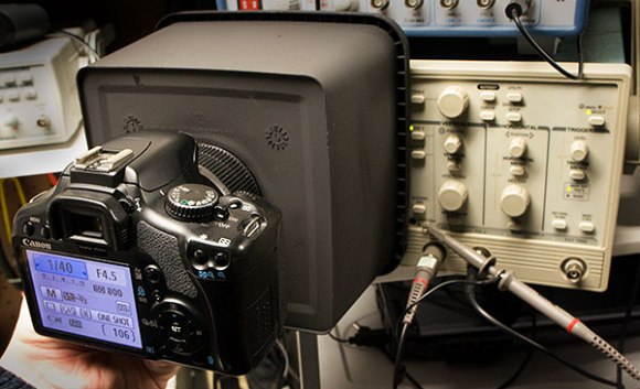
[Alan] posted a video tour of his electronics shop, but you’ll be viewing it through the green screen of an oscilloscope. The image above is a video camera filming a scope screen which displays the image of…. an oscilloscope (insert your own Yo Dawg meme here). But first he shares the technique he uses to display composite video on an oscilloscope screen.

The first three minutes of the video after the break are devoted to the video display hack. He starts with a glimpse of the breadboard circuit which takes the composite video signal and provides the necessary X, Y, and Z input signals to the scope to perform like this. He then walks through each portion of the schematic, which is based on an LM1881 video sync separator chip. The horizontal and vertical sync signals are separated by this chip, then filtered to produce ramp voltages for each to drive X and Y. The Z-axis is fed through a simple inverter circuit; Bob’s your uncle and your oscilloscope is now a TV monitor.

Of course this is not the first time this has been done. But we loved [Alan’s] presentation, and thought the shop tour was a fun way to finish off the video.

Continue reading “Watch A Shop Tour Through The Screen Of An Oscilloscope”

Rabiscoscopio – Oscilloscope Drawing Made Easy

Rabiscoscopio

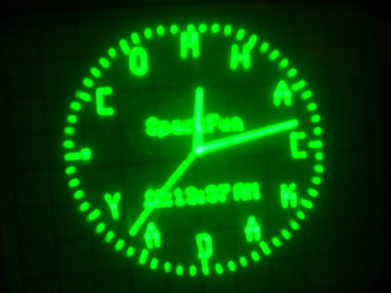
If you own an oscilloscope, sooner or later the urge to see something other than signals on the screen will strike. Some people ignore the urge and go about their normal business while others give in, spending hours carefully crafting images, games, and more. The process is time consuming and tricky as our own [Kevin Dady] discovered, but rewards come in the form of geek cred and are hard to pass up.

[Alex] wanted to draw on his oscilloscope, but decided that he would try something other than the microcontroller-based solutions we have seen in the past. He figured the easiest and most accessible way to draw on the scope was with sound, so he whipped up a small application he calls Rabiscoscopio to do most of the work for him.

He starts off by drawing an image using a single line, saving it as an SVG file. This image is converted into an audio file by Rabiscoscopio, which can then be fed directly into his oscilloscope from his PC. That’s all there is to it – it really doesn’t get much easier.

While you could claim that [Alex] is cheating his way through the oscilloscope drawing process, we think his application rocks – after all, hacking is about making your technology work for you rather than the other way around.

Give Rabiscoscopio a try and post the results here or in our Flickr stream – we’d love to see what you guys come up with.

In the meantime, check out the video below to see [Alex’s] attempt at replicating the Garoa Hackerspace logo on his scope.

Continue reading “Rabiscoscopio – Oscilloscope Drawing Made Easy”

Grabbing Data From A Rigol ‘scope With Python

While a fancy Rigol 1052E oscilloscope is a great tool and a wonderful portable oscilloscope we heartily recommend, sometimes you just need to use the more ‘advanced’ functions of an oscilloscope. Luckily, [cibomahto] figured out how to use a Rigol scope with Python, allowing for easy remote viewing and control of a Rigol 1052E ‘scope on any desktop computer.

[cibomahto]’s Python script grabs the screen and can send commands to the oscilloscope, effectively obviating the need for the slightly-terrible Rigol Ultrascope software. Not only that, controlling the 1052E is possible under OS X and Linux because of the portable Python nature of [cibomahto]’s work.

The Rigol DS1052E has become the de facto standard oscilloscope to grace the workbenches of makers and hackers around the globe. With a small price tag, the ability to double the bandwidth, and an active homebrew development scene, we doubt [cibomahto]’s work of grabbing data over USB will be the last hack we’ll see for this fine machine.

Thanks to [Markus] for sending this one in.

Hackday Links: March 10, 2012

We’re throwing money at our monitor and nothing’s happening!

Sometimes we get hacks sent into our tip line that are outrageously awesome, but apart from a YouTube video we’ve got nothing else to write about. So begins the story of the flying Back to the Future DeLorean quadrocopter. Sadly, the story ends with the video as well. (If you’ve got any info, send it in!)

Fine, we’ll throw in another cool car

Mercedes covered a car with LEDs and made the James Bond’s invisible car from Die Another DayThe Mercedes video cost tens of thousands of dollars to produce, so of course there’s camera trickery; we’re just wondering how much credit Adobe After Effects gets for this build.

Microsoft touchscreen demo might be impossible

Yes, Microsoft does care about user experience. Just take a look at this video from their applied sciences group. They did user testing with touchscreens that updated every 1 millisecond, compared to the ~100ms our phones and tablets usually update. Of course the result was a better UX, but now we’re wondering how they built a touch screen that updates every millisecond? That’s a refresh rate of 1 kHz, and we’ve got no clue how they bodged that one together. We’re probably dealing with a Microsoft Surface projector/IR camera thing here, but that doesn’t answer any questions.

Edit: [Philip Rowney] sent in a tip that it could be this TI touch screen controller that can sample above 1 kHz. The only problem is this chip uses a resistive touch screen, instead of a multitouch-enabled capacitive screen. At least that solves one problem.

And now for something that can measure 1 kHz

[Paleotechnologist] posted an excellent guide to the care and feeding of an oscilloscope. Most of our readers probably already know the ins and outs of their awesome Techtronix and HP units, but that doesn’t mean the younglings won’t have to learn sooner or later.

Good idea, except the part about saving it for spring

In a moment of serendipity, [Valentin] figured out how to use touchscreens with wool gloves. The answer: rub thermal grease into the tip of the index finger. It works, and doesn’t look to be too much of a mess. We’ll remember this for next winter.

The last one didn’t have a picture, so here’s this

[Darrell] used a little bit of LaTeX and Ruby to make colored labels for his resistor collection. We’re struck with the idea of using test tubes to organize resistors. It’s cool and makes everything look all sciencey and stuff.

3D Graphics On An Oscilloscope

Armed with four wingtip-mounted Sienar Fleet Systems L-s9.3 laser cannons and a SFS P-s5.6 twin ion engine, the TIE Interceptor has become the scourge of the Rebel fleet, nearly capable of out-running and out-maneuvering the beloved A-wings of Nomad Squadron. Because of [Matt]’s tireless work, we can now visualize TIE Interceptors on approach with our targeting computers oscilloscopes.

[Matt]’s oscilloscope visualization of a TIE fighter is a huge improvement on previous scope displays we’ve seen, considering [Matt] used very minimal hardware to display 3D graphics. The build uses an ATMega88 along with a 10-bit DAC to draw lines on the screen. The capacious Mega88 with 8kB of flash and 1kB of SRAM was nearly filled to capacity with [Matt]’s project; to improve the rendering speed of the display, sine & cosine values are pre-computed and stored in flash along with division tables for common values.

The rotation of the TIE fighter is controlled by a serial connection to [Batt]’s desktop. It’s a very impressive piece of work that looks like it would fit into the cinematic aesthetic of The Empire Strikes Back. Check out [Matt]’s video of the TIE rotating in space after the break.

Continue reading “3D Graphics On An Oscilloscope”