Toner Transfer Explained Step-by-step

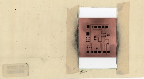
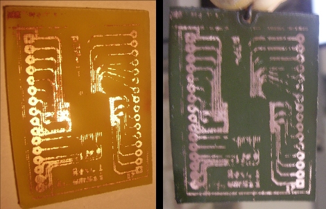
[Tanjent] send us a link to his tutorial on the toner transfer process for fabricating circuit boards. We’ve seen a lot of these in the past, but we liked how his is straight to the point while also sharing several tips and options along the way. Notably, he ”tints” the copper clad before trying to adhere the toner to it by swabbing on a bit of etchant. His reasoning for this is that the toner has more trouble sticking to the shiny copper. Just a bit of etchant will pit the surface and let the toner stick better.

He’s still using paper as a medium and not printing toner powder directly to the copper clad. His paper of choice is HP Brochure Paper while we use glossy pages from the union newspaper. But like us, he does use copper chloride as an etchant, which you can learn to make yourself. We’re still looking for a definitive solution for disposing of this chemical. We’ve been using the same batch for years and recently it’s turned cloudy with impurities. If you’ve got disposal tips let’s hear them in the comments section.

Print Toner Directly To A PCB

We use the toner transfer method to fabricate printed circuit boards. The most difficult part of this is printing, ironing, and removing the paper from the toner that is used as an etchant resist material. [Mark Lerman] is developing a method to apply toner directly to the copper clad using a laser printer. Each of the photos in his gallery have comments that take us through his process. A laser printer has been modified to negatively charge the copper plate, thereby attracting the positively charged toner to it. Once the toner has been applied, the board is baked in an oven, then run through a laminator. This process can yield 2 mil traces and it looks like the potential for incredibly clean boards is just around the corner. The question is, will this be easier and take less time than using photo resist?

We’ve contacted [Mark] in hopes of getting more details. If you can’t wait for a follow-up, take a look at this thread concerning his work.

[Thanks Komradbob]

Get Serious About Building A Sequencer

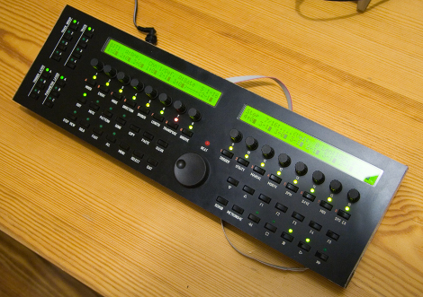
This is the fourth generation MIDIbox sequencer which has a features set that’s several screens long. We’ve embedded the teaser video of this 16-track marvel after the break. You can use it via a traditional MIDI connection or with USB. Standalone Ethernet features are also in the works. It’s fully documented and you can etch your own PCB if you’re brave but it might be easier to get in on the group PCB buy if you just have to have one of these. There’s no all-in-one kit, but that will just make the taste of success sweeter once your soldering iron cools down.

Continue reading “Get Serious About Building A Sequencer”

PICMAN, A Diy Prototyping Setup

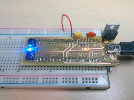
[Ytai Ben-Tsvi] wanted a rapid prototyping tool that could be easily and cheaply built at home. He came up with the PICMAN, a breadboard compatible PIC based board that has everything you need to get the ball rolling. He’s using a PIC18LF4553 which has built-in USB support that can be used with a bootloader for programming. The board also features a voltage regulator for non-USB power sources, some indicator LEDs, a user-defined button, and a reset button. The chip is on the underside and a combination of through-hole and surface-mount parts make for a one-sided PCB that can easily be etched using the toner transfer method. You will need a PIC programmer to burn the bootloader firmware the first time but once that’s done this becomes a self-contained package.

Home Fabricated Boards In Any Color

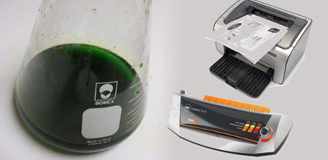
Tired of every printed circuit board you etch coming out brown? Take a page out of [Dane’s] book and dye your PCB to just about any color you want. One hour submerged in a 200 degree bath of Rit dye turned his brown FR4 substrate to the desired dark green. We give him points for being dangerous enough to use a broken bottle as a vessel, yet wearing eye protection at the same time.

We never really thought of doing this, but it’s pretty interesting that it works. We’ve stained the substrate when removing etch resist so this should have been obvious, but wasn’t.

Laser Cutting Solder Stencils

Do you have access to a laser cutter? If so, you can use [Riley Porter’s] method to cut your own solder stencils. He starts with the Eagle files and exports the Dimension and tCream layers to a PDF. That file is then processed using Ghostwriter, Gview, and finally, Corel draw. The result is a 1200dpi file to feed to your Epilog laser. Now you’re ready to stencil on the solder paste and populate the PCB.

[Thanks Travis Goodspeed]

PCB Drill Press On A Budget

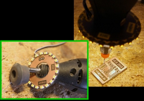
An accurate drill press is an essential tool for making your own through-hole printed circuit boards at home. Reader [Josh Ashby] offers up a solid design using scrap bin materials.

A major issue with PCB drilling is that even the slightest horizontal play will snap the delicate carbide drill bit. Hobbyist-grade tools such as Dremel’s drill press attachment are usually too sloppy for this task, while a more precise instrument might set you back a couple hundred bucks.

[Josh’s] design uses a nylon “sled” moving vertically in an aluminum u-channel track. Most of these materials were salvaged or were acquired inexpensively from a local hardware store, and assembled in less than a day. Surprisingly, this low-tech approach has proven sufficiently smooth that he’s yet to break a bit while drilling. And the entire setup, including the knockoff Harbor Freight rotary tool, cost less than the wobbly name-brand accessory alone.