Receiving Asynchronous Data Bursts

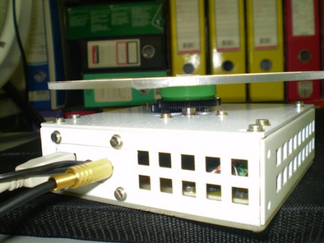
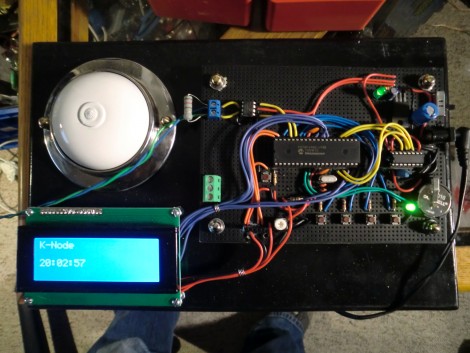
[Johan’s] been working on a chunk of code for about seven years and he thinks it’s ready to help you with your next project. He calls it D1 (The One) and it lets you receive asynchronous data without the need for a hardware USART. It’s capable of working with signals from an IR or RF remote, as well as tangentially related transmissions like RFID and magstripe readers.

It uses timer and port interrupts to sample the incoming data. Once it’s captured a transmission, the code sets a flag so that you can pull what it got into your own application. If you’re expecting to receive a protocol that sends packets several times in a row a verification module is also included which runs as a precondition of setting the received flag. The package is written in PIC assembly, but with all the information that [Johan] included in his post this shouldn’t be hard to port over to other chip architecture.

Tiny N64 Controller Comes With Hand-cramp Guarantee

Just looking at this little thing makes our hands ache. But [Kirren] did do a great job of building an N64 controller inside a tiny project box. It’s not a mod, but a ground-up build based on a PIC 16F628 microcontroller.

It has most of the buttons found on a standard controller, and he assures us that you can play most games without missing the ones that didn’t make it into the design. You can just make out the analog stick to the left, but that silver ring on the right is actually a 4-direction tactile switch which stands in for the C buttons. He’s also included Start, A, B, R, and Z.

The link above goes to his Wiki, and there are more than enough details if you’re interested in doing this yourself or just understanding how everything works. Check out his writeup on the protocol, and  you can even get a copy of his code. There’s also a video demo after the break which shows [Kirren] playing some Bond with the controller. Continue reading “Tiny N64 Controller Comes With Hand-cramp Guarantee”

Automated Turntable Photography

[Muris] has a friend who is selling items on the internet. This friend wanted a simple way to make rotating images of the products and asked him to help. The result of his labors is this base unit that drives the turn table and controls the camera.

The first iteration of the turntable was powered by the stepper motor from a floppy drive. A disc was mounted directly on the motor spindle, but the results were a bit poor. This is because the motor had a fairly low resolution of 200 steps per rotation. That doesn’t allow for smooth animation, and there was a lot of vibration in the system. An upgrade to the geared system you see above included swapping out that motor for one from an old scanner. Now it achieves 1200 steps per rotation and the vibration is gone.

The connectors seen in the base are USB, incoming power, and shutter control. [Muris] wrote a program to control the PIC 16F628A inside the base. The program sends commands via USB and has parameters for number of frames per rotation, direction of rotation, and the like. Set it up as desired, place the product on the turntable, and hit start. Unfortunately there’s no video of this in action because [Muris] gave it to his friend as soon as it was finished. We guess the fact that he didn’t get it back means it’s working great.

If you don’t mind some rough edges and exposed wiring you can throw a system of your own together pretty quickly.

Wireless Door Alarms Protect Your Stuff From Afar

wireless-shed-alarm

[Webby] had a friend named [Steve], and as the story goes [Steve] had a few storage sheds on his property that were prone to break-ins.

While the doors were all fitted with a lock, wooden doors are only so strong, and are easy fodder for intruders bearing crowbars and the like. [Steve] was looking for a good way to know when people were poking their heads where they don’t belong, so he rigged up a set of simple alarms that let him know when it’s time to break out the shotgun.

On each of the shed doors, he installed a small IR proximity sensor wired up to a PIC12F675 microcontroller. The PIC is is connected to the “call” button a medium range wireless radio, so that whenever the IR sensor detects that the door is ajar, the PIC triggers an alert on the base unit.

The solution is simple, which we figure also makes it pretty reliable – nice job!

CAN Bus For Home Automation

Here’s one node on the new home automation system on which [Black Rynius] is working. So far he’s testing out the system with just two nodes, but plans to build more as the project progresses. He’s chosen to use the CAN bus for communications; a protocol which is most commonly found in automotive applications.

The biggest plus about using the CAN bus is that it requires just one pair of wires for communications. As you can see, there’s an old doorbell included on this board and he’s hoping to use the existing doorbell wire to connect between nodes. Each unit includes a PIC 18F4580 which has a CAN engine built into it for easy protocol translation. There is also an MCP2551 which handles the transmissions. You can read a bit more about the hardware choices in his breadboarding post.

So far almost everything is working as planned. He’s able to send and receive data between the two boards including temperature from a sensor and time from a DS1305 RTC chip. The one thing that vexes him is that doorbell. It draws too much current for the wall wart that’s powering the board, browning out the microcontroller and causing a reset. That’s not a hard fix and we look forward to more developments in the near future.

[via Dangerous Prototypes]

Dual-monitor Work Stations Aims To Keep You On The Treadmill Longer

In an effort keep his workout schedule on track [Jamie] built himself this dual-screen treadmill work station. He picked up the treadmill for about $50 on eBay, and after some follies with its shoddy construction, ended up with a pretty nice setup.

The first rendition of this project was just a wooden shelf to hold a laptop. But after the treadmill fell apart, sending his laptop tumbling, he reinforced the machine and added a bunch of stuff in the process. There’s now some custom electronics used to track his progress. He painted a white square on the black belt that makes up the running surface. That is monitored by a PIC microcontroller via a phototransistor and op-amp. He uses a USB data acquisition card to feed the belt-revolution count to the computer for use in tracking his workouts.

The presence of a computer in his setup would make Internet logging a snap too. The exercise bike we looked at on Saturday used a direct Ethernet connection for its logging, but [Jamie’s] setup could be used in the same way. He just needs a script to bridge the collected data with an Internet logging site’s API.

DIY Intervalometer Uses A Great Looking Enclosure

That finished look for your project is all about the enclosure you find to host it. We think [Punge] really did a great job with the case for this DIY intervalometer. The build section of the project page links to the company that makes the enclosures. They’re meant to host round PCBs with several options for button configuration. Combine this with enough space for a coin cell and you’ve got a great looking custom device.

The intervalometer itself is much like others we’ve seen. It uses an audio-jack connector to control the camera. You have the option of using a three or four contact version depending on what your camera supports. The PIC 12F683 uses an optocoupler with a built-in transistor to do the switching. A single button seen at nine o’clock on the board above is all it takes to start the device off. Press and hold once to wake it up, then wait for your desired interval and press the button again to start the timed shots.

You’ll notice that there is no programming head in this design. A separate board was etched to attach the PicKit, with the surface mount chip just held in place during programming.