Retro TO-3 Switching Voltage Regulator

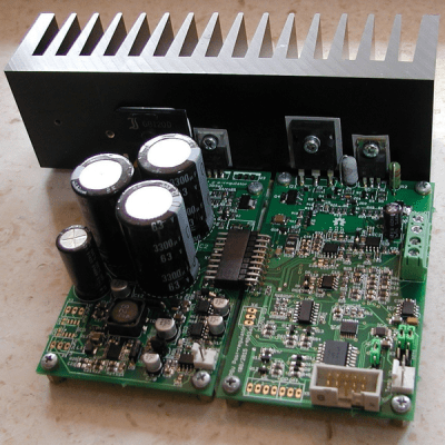
Restoring old gear often means replacing unavailable parts with modern equivalents. [Alex Eisenhut] needed to replace some old TO-3 voltage regulators and decided to make an authentic-looking switching power supply replacement. These three pin metal cans were very common, especially the LM340 5V regulator which was, of course, a linear regulator. Today, you are more likely to see a 7805 in a TO-220 case or something surface mount for a comparable linear regulator.

As you might expect, the board uses surface mount components. [Alex] used Mill Max machine pins to match the original regulator footprint and calls the regulator Ton3y. He plans to cover it up with a 3D printed lid, but it seems a shame to hide the fine PCB work.

In the pictures, you can see that the machine pins are a tight fit. [Alex] used a hammer to lightly tap them into place. Of course, the original TO-3 regulators were linear and would generate a lot of heat. The Ton3y, as you’d expect from a switching power supply, runs cool (according to the scientific measurement made with [Alex]’s pinky finger) and surely has a wider input voltage range and more output current capacity.

We’ve seen replacement switching regulators before, but this one is really a work of art.

Hackaday Prize Entry: A Better Bench Power Supply

Back in February, [The Big One] started building the bench power supply to rule them all. His previous power supply was just an ATX computer power supply. It worked, but that didn’t give him fancy stuff like different channels of individually adjustable voltages. Since then, we’ve spun up the 2015 Hackaday Prize, and [The Big One] has changed his DIY power supply into a Hackaday Prize entry that competes well against $1000 mid-range commercial units.

The single most expensive component in this power supply are a pair of isolated switched power supplies rated for 15V and 7A. This is a change from [The Big One]’s original plan to use a big ‘ol transformer; a switched mode supply is smaller, lighter, costs about the same, and is much better suited to the modular nature of the project.

The final design for this power supply has some interesting features: up to six channels are possible, voltage and current can go all the way down to zero, and everything can be controlled over USB. Those are amazing features that won’t be found in any $100 cheapo bench power supply, and [The Big One]’s amazing documentation for this project makes it a perfect entry for The Hackaday Prize.

The 2015 Hackaday Prize is sponsored by:

Power Supply

Making Your Own Laser Cut PSU

[Csaba] and his friend bought a 600W switching lab-style power supply unit off eBay a while ago, and after about a year of tangled wires and mess, finally decided to enclose it in a fancy box.

The PSU itself required some modification as it was just a controller and a power board — so they added a dedicated mains transformer, and a buffer capacitor. The housing is made out of 3mm plywood which they designed and laser cut specifically for the PSU — and it looks fantastic.

It includes a cooling fan, a small digital display and a whole bunch of controls for finely tuning your electronics power requirement — take a look at the demonstration video after the break.

Continue reading “Making Your Own Laser Cut PSU”

How To Reverse Engineer A PCB

For [Peter]’s entry for the 2015 Hackaday Prize, he’s attempting to improve the standard industrial process to fix atmospheric nitrogen. Why? Fertilizers. He’s come up with an interesting technique that uses acoustic transducers in a pressure vessel, and to power that transducer, he’s turned to the greatest scrap heap in the world: eBay. He found a cheap ultrasonic power supply, but didn’t know offhand if it would work with his experiments. That’s alright; it’s a great opportunity to demo some basic reverse engineering skills.

A few months ago, [Dave Jones] posted a great video where he reverse engineers the front end of the new Rigol Zed. The basic technique is to make a photocopy, get some transparency sheets, grab a meter, and go to town. [Peter]’s technique is similar, only he’s using digital image manipulation, Photoshop, and a meter.

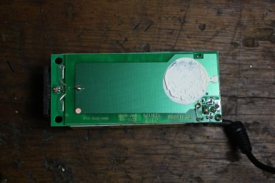
The process begins by taking pictures of both sides of the board, resizing them, flipping one side, and making an image with several layers. The traces on the bottom of the board were flooded and filled with the paint bucket tool, and components and traces carefully annotated.

With some effort, [Peter] was able to create a schematic of his board. He doesn’t know if this power supply will work with his experiments; there’s still some question of what some components actually do. Still, it’s a good effort, a great learning opportunity, and another log in [Peter]’s entry to The Hackaday Prize

The Modular Bench Power Supply To Rule Them All

Right now, [The Big One] is using an ATX power supply as a bench power supply for all his electronics projects. It works, but it’s not ideal. The next step up from a power supply from an old computer is, in order, one of those Chinese deals on Amazon, a used HP supply, or for the very cool people among us, building your own. [The Big One] is very, very cool and he’s building the modular bench supply to rule them all.

This is not your $100 china special power supply that [The Big One] would have to buy again in a few months. Inside this massive power supply is a massive transformer and rectifier that fans out to multiple power supply modules. The modules themselves will be based on an OPA548 that will be able to supply up to 3A with current limiting.

Each of these channels will be controlled by an ATMega32u4, with all the fancy stuff you’d expect from the ultimate supply; USB for setting voltage, current, and logging data, a nice LCD character display, and it’s surprisingly cheap; just about $100 for the transformer, and about $50 for each module.

It’s shaping up to be a great build, and with all the features, a power supply that would also make a great kit. If you have any input you’d like [The Big One] to hear, let him know on the project page.

A Primer On Buck (and Boost) Converters

We all know that the reason the electrical system uses alternating current is because it’s easy to step the voltage up and down using a transformer, a feature which just isn’t possible with a DC system… or is it? Perhaps you’ve heard of mysterious DC-DC transformers before but never really wanted to look at the wizardry that makes them possible. Now, SparkFun Director of Engineering [Pete Dokter] has a tutorial which explains how these mysterious devices work.

Known as buck converters if they step the input voltage down and boost converters if they step the voltage up, [Pete] explains how these circuits exploit the properties of an inductor to resist changes in current flow. He goes into exquisite detail to explain how components like transistors or MOSFETs are used to switch the current flow to the inductor very rapidly, and just exactly what happens to the magnetic field which makes these devices possible.

The video gives a good amount of background knowledge if you’ve always wanted to understand these devices a little bit better. There are also a few projects floating around that exploit these devices, such as one that uses an AVR microcontroller to perform the switching for a small circuit, or another that uses the interesting properties of these circuits to follow the I-V curve of a solar panel to help charge a bank of batteries. The possibilities are endless!

Continue reading “A Primer On Buck (and Boost) Converters”

A low cost power supply unit with displays

A Low Cost Bench Supply

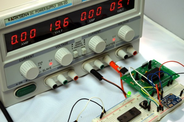
Everyone needs a power supply on their bench, but a standard lab supply isn’t cheap. [ludzinc]’s PSU Console is a cheap alternative, which provides the basic features you’d expect in a lab supply.

The basis of this PSU is a DC/DC module based on the LM2596 step down switching regulator. These modules cost less than a single LM2596, but have all the required components for a buck DC/DC converter. Sure, they might not last forever, and they’re not the most efficient regulators, but the price is right.

The front panel has four displays for voltage and current, which are just low cost voltmeter displays. The potentiometers are used for adjusting the voltage of the DC/DC, and controlling the current limiter. This limiter monitors current through a shunt, and shuts off a MOSFET when the limit is exceeded.

The final product looks like something that’s ready for daily use, and was much cheaper than most supplies with these features. These low cost DC/DC modules are worth a look if you’re considering a similar build.