 Anyone with an inkling of interest in super-sized remote control aircraft probably has at least seen some of the mind-blowing projects that [Ramy RC] has worked on over the years, with examples like the ongoing Airbus A380-800 build approaching the size of a full-sized business jet. That said, they recently got the offer to build a flying prototype of the Natilus Horizon, a blended wing body (BWB) aircraft that’s currently being developed into a full-sized production aircraft.
Suffice it to say that BWB RC aircraft isn’t something that they have built before, but as co-founder of Natilus, [Aleksey Matyushev], explains, they want to prove in this manner that building scale prototypes of future production aircraft is not nearly as complex as it’s often made out to be. Meaning that even two blokes in a shed as is the case here should be able to pull it off.
Natilus was founded in 2016 amidst strongly rising interest in these BWB aircraft designs that may one day threaten today’s tubes-with-wings. Their Kona design would be the cargo version and this Horizon prototype that [Ramy RC] is building the passenger version.
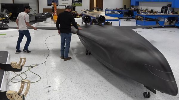
In this first video of two total, we can see the CAD project of the prototype and how the basic aircraft structure is being constructed out of carbon fiber composite, wood and foam. To this the engine nacelles, landing gear and wings are mounted, readying it for its maiden flight. The Natilus engineers have previously done all the simulations that should mean that it’ll fly like a glider, but we will have to wait until the next video to see whether that is the case.
Continue reading “Building A Flying Blended Wing Body Aircraft Prototype”