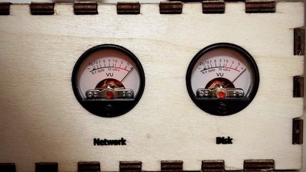
Snazzy analog meters can lend a retro flair to almost any project, but these days they often seem to be retasked as indicators for completely different purposes than originally intended. That’s true for these Vu meters repurposed as gauges for a Raspberry Pi server, and we think the build log is as informative as the finished product is good-looking.
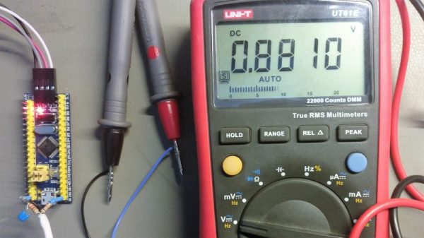
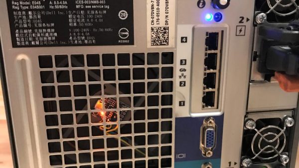
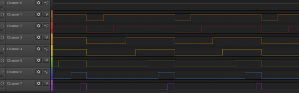
As [MrWunderbar] admits, the dancing needles of moving-coil meters lend hipster cred to a project, but getting his Vu meters to cooperate and display network utilization and disk I/O on his Raspberry Pi NAS server was no mean feat. His build log is full of nice details on how to measure the internal resistance of the meter and determine a proper series resistor. He also has a lengthy discussion of the relative merits of driving the meters using a PWM signal or using a DAC; in the end, [MrWunderbar] chose to go the DAC route, and the video below shows the desired rapid but smooth swings as disk and network usage change. He also goes into great depth on pulling usage parameters from psutil and parsing the results for display on the meters.
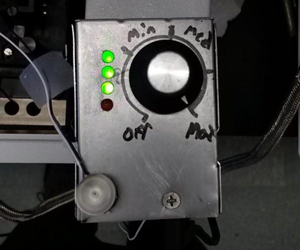
Looking for more analog meter goodness? We saw a similar CPU load meter a few months back, and there was this mash-up of Nixies and old meters for a solar energy CEO’s desk.
Continue reading “Repurposing Moving Coil Meters To Monitor Server Performance”