There’s a bunch of different electric scooters available nowadays, including those hoverboards that keep catching fire. [TK] had an older Razor E300 that uses lead acid batteries. After getting tired of the low speeds and 12 hour charge times, [TK] decided it was time to swap for lithium batteries.
The new batteries were sourced from a Ryobi drill. Each provides 18 V, giving 36 V in series. The original batteries only ran at 24 V, which caused some issues with the motor controller. It refused to start up with the higher voltage. The solution: disable the safety shutdown relay on the motor controller by bridging it with a wire.
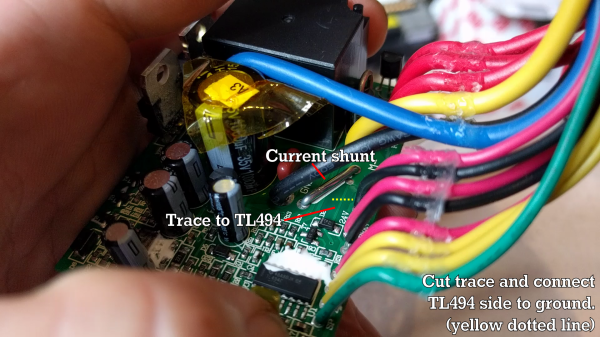
With the voltage issue sorted out, it was time for the current limit to be modified. This motor controller uses a TI TL494 to generate the PWM waveforms that drive a MOSFET to provide variable power to the motor. Cutting the trace to the TL494’s current sense pin removed the current limit all together.
We’re not saying it’s advisable to disable all current and voltage limits on your scooter, but it seems to be working out for [TK]. The $200 scooter now does 28 km/h, up from 22 km/h and charges much faster. With gearing mods, he’s hoping to eke out some more performance.
After the break, the full conversion video.
Continue reading “Converting An Electric Scooter To Lithium Batteries And Disabling The Safeties”