Anyone with a record player is familiar with the concept of translating irregularities on a surface into sound. And, anyone who has ever cracked open a CD player or DVD player has seen how a laser can be used to reproduce sound digitally. Combining the two would be an interesting project in its own right, but [Dimitry Morozov] took this a couple of steps further with his pyrite disc sound object project.
 Pyrite discs, also known as pyrite suns or pyrite dollars, are a form of pyrite in which the crystallization structure forms a disc with radial striations. Pyrite discs are unique to the area around Sparta, Illinois, and are generally found in coal mines there. They have no real practical use, but are a favorite of mineral collectors because of their interesting aesthetics.
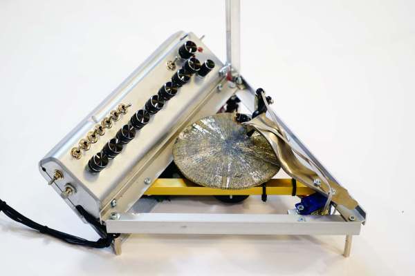
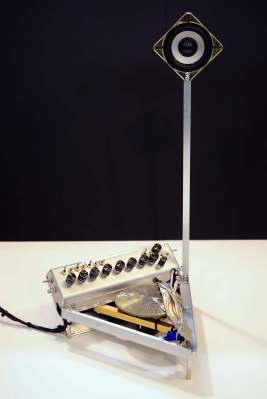
[Dmitry] received his pyrite disc from one such mineral collector in Boulder, CO, with the request that he use it for an interesting project. [Dmitry] himself specializes in art installations and unique instruments, and combined those passions in his pyrite disc sound object called Ra.
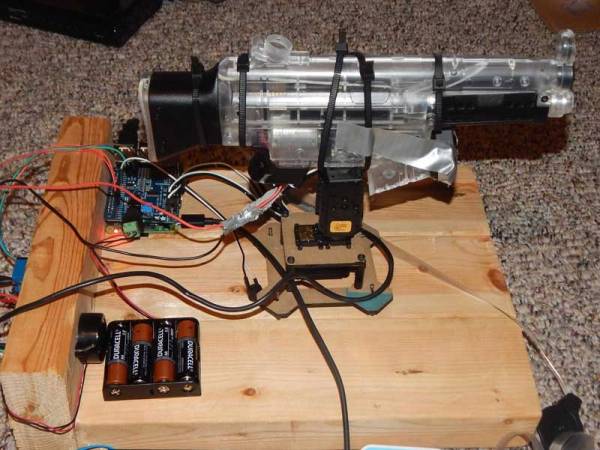
The concept itself is straightforward: spin the pyrite disc and use a laser to convert the surface striations into audio. But, as you can see in the photos and video, the execution was far from straightforward. From what we can gather, [Dimitry] used an Arduino Nano and a DIY laser pickup on a servo arm to scan the pyrite disc as it’s being spun by a stepper motor. That data is then sent to a Raspberry Pi where it’s synthesized (with various modulation and effects controls), to produce sound that is output through the single speaker attached to the object. Generating sound from unusual sources is certainly nothing new to regular readers, but the beauty of this part project is definitely something to be applauded.
Continue reading “Spinning A Pyrite Record For Art” →