Creating A Multimedia Elevator Ride

[Ben Peoples] works in theatrical electronics. Sounds like fun, and here’s an example of the kind of stuff he does. We’re not sure what event this installation was used for, but if the elevator ride needed something flashy just think of what the party room must have looked like. These HDTV screens on the ceiling of the elevator play different clips when the elevator is moving up or down. The challenge for [Ben] was to find a way to make it work without tapping into the elevator electronics or requiring any button presses.

The first attempt at sensing the elevator’s travel was done with an accelerometer. The problem with this approach is that an accelerometer only senses change in acceleration and this method proved to be fairly error prone. [Ben] switched over to a reflective sensor which performed quite well. Since most of these sensors will only work within about an eighth of an inch he ended up building his own with a LDR and a couple of amber LEDs.

[via Reddit]

Simple Proximity Sensor

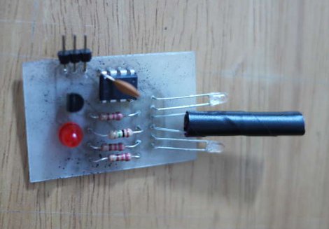
[Dustin Andrews] built this add-on board which works as a proximity sensor. He wanted a standalone sensor for his Arduino projects which would use a single pin as a trigger. This lets him alert the Arduino when an object approaches the sensor without the need for polling or extra code on the Arduino side of things.

As you can see, a single chip on the board takes care of all the work. That’s an ATtiny13, they’re inexpensive and sometimes you can even salvage them from consumer electronics like this color changing light bulb. The microcontroller monitors the phototransistor which is wrapped in electrical tape to isolate it from the IR LED emitters on either side. This setup creates a reflective sensor. When an object nears the board, the infrared light from the emitters reflects off of it and onto the phototransistor. And since the Arduino works as an AVR programmer you don’t need special hardware to program the device.

Hexbug Code Rewrite Makes It A Walking Line-follower

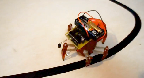
You know you’ve got a good hardware platform if you can easily repurpose it with a code rewrite. And that’s what [Eric] continues to do with these little Hexbugs. This time around he’s bent the IR emitter and receiver downward to use as a reflectance sensor. This gives it the ability to follow a dark line on a light surface.

He originally patched an MSP430 into the $25 RC toy. The IR pair was intended for obstacle avoidance, which we saw in a recent links post. This hack does a great job of repurposing the avoidance system. Since the add-on hardware is mounted on a motorized turret, the single sensor pair can sweep back and forth to find the line it will follow. In one way this is better than most line followers which use multiple sensors mounted to the body. But the drawback is that this results in slower travel and won’t be winning any contests. Don’t miss the demo clip after the break.

Continue reading “Hexbug Code Rewrite Makes It A Walking Line-follower”

Cloud Mirror Adds Internet To Your Morning Ritual

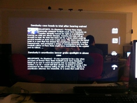
This mirror has a large monitor behind it which can be operated using hand gestures. It’s the result of a team effort from [Daniel Burnham], [Anuj Patel], and [Sam Bell] to build a web-enabled mirror for their ECE 4180 class at the Georgia Institute of Technology.

So far they’ve implemented four widget for the system. You can see the icons which activate each in the column to the right of the mirror. From top to bottom they are Calendar, News, Traffic, and Weather. The video after the break shows the gestures used to control the display. First select the widget by holding your hand over the appropriate icon. Next, bring that widget to the main display area by swiping from right to left along the top of the mirror.

Hardware details are shared more freely in their presentation slides (PDF). A sonar distance sensor activated the device when a user is close enough to the screen. Seven IR reflectance sensors detect a hand placed in front of them. We like this input method, as it keep the ‘display’ area finger-print free. But we wonder if the IR sensors could be placed behind the glass instead of beside it?

Continue reading “Cloud Mirror Adds Internet To Your Morning Ritual”

UPDATE: Playing Piano With Optical Sensors

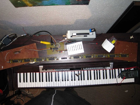
[Sebastian Steppeler] has been hard at work on his optical sensors for an electric piano. When we looked in on the project back in October he was testing reflective sensors to increase responsiveness and MIDI data resolution for his electric keyboard. Since then he’s finalized the sensor circuits and produced enough boards to monitor all 88 keys on this full keyboard. You can see the string of PCBs just above the ivories, waiting to be installed. Not only are then in, but he also added sensors for the pedals.

Because the boards were installed by hand, there are some variances in the physical placement. This can have a rather dramatic effect on the readings from the reflective sensors so he has been working out a method of balancing the calibration. Part of this is already being taken care of by the C# interface that he wrote for a PC. Take a few minutes to check out all of his blog posts, then jump down after the break and hear how great it sounds.

Continue reading “UPDATE: Playing Piano With Optical Sensors”

Measuring RPM With Reflective Sensors

[Arao] wanted to measure the RPM of a spinning wheel using parts that he could scavenge from his junk box. A bit of thought led him to build a reflective sensor which can measure the spinning of a wheel (translated).

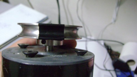
He got his hands on an infrared phototransistor which had been used as part of the remote control for some consumer electronics. Snooping around with his multimeter helped him establish the pin out of the device. By positioning an IR LED inside of a shroud, yet adjacent to the phototransistor, he can measure the intensity of the LED’s light as it is reflected off of nearby surfaces. The pulley seen above has a piece of electrical tape on it. When this passes by the LED, less of the infrared light is reflected and the drop in intensity is picked up by the phototransistor. [Arao] made the system rock-solid by rolling an LM358 op-amp into the circuit. He’s posted the schematic as well as some screen shots from an oscilloscope during testing.

The Concepts Behind Robotic Maze Solving

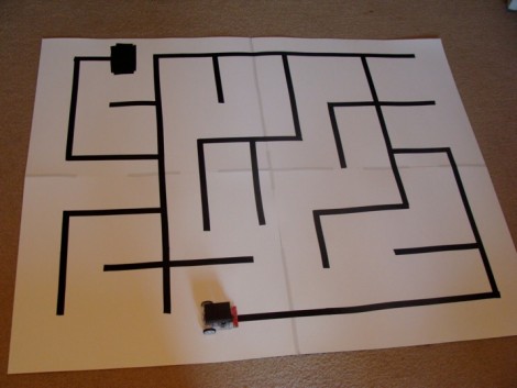
[Patrick McCabe’s] latest offering is a well-built maze-solving bot. This take on the competitive past-time is a little more approachable for your common mortal than the micro-bot speed maze solving we’ve seen. Don’t miss seeing the methodical process play out in the clips below the fold.

The playing field that [Patrick’s] robot is navigating is made up of a electrical-tape track on a white background. The two-inch tall double-decker bot is every economical. It uses an RBBB Arduino board to read an optical reflectance sensor array made by Pololu, then it drives a couple of geared motors using an L293D h-bridge breakout board. But we already know that [Patrick’s] a talented robot builder, this time around we’re happy to see his in-depth discussion of how to program a robot to solve a maze. In it he covers all of the different situations your robot might face and how to deal with them. Once you’ve dug through all of the concepts, dust off that bot you’ve got lying in the corner and start writing some new firmware.

Continue reading “The Concepts Behind Robotic Maze Solving”