Audio Output Selection Courtesy Of The Internet

[Peter] was tired of crawling behind his desktop computer to switch between headphones and speakers. We feel his pain, as the headphone port on our computer speakers has its own demonic hum rendering the jack useless to us. His solution was to build this output selector board, then control it via the network.

A relay is responsible for routing the single input to one of two outputs. One output is wired to the normally closed pin on the relay, the other to the normally open pin. The important thing here is to make sure you have a separate audio ground so as not to pick up noise from the rest of the hardware.

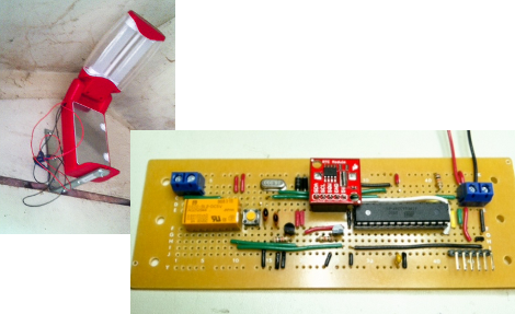
What you see above is only the switching circuitry. This is where [Peter] went a little overboard, using an Arduino along with an Ethernet shield to drive the relay via a transistor. For this particular application there must be an easier way. But if you’re working on home automation from your smart phone, this might be just the thing to make your audio setup browser-controlled.

[via Build Lounge]

Chicken Light Keeps Up Egg Production

It turns out that as the days get shorter, chickens lay fewer eggs. But you can trick them into keep up production using artificial light. [Jpitz31] decided to build his own timed coop light to bridge the gap until the days of plentiful sunlight return.

He already had an LED camping light to use, but needed to find a way to power it and to switch it on and off on a schedule. He chose an ATmega328 for the latter, as he had a bunch of extras sitting around. As for power, there isn’t AC available where the coop is, so he opted for a 12V lead-acid battery with hopes of adding solar charging features in the future.

Switching is handled by a relay, with accurate time kept by a DS1307 real-time clock (it’s the red PCB seen above). Everything fits nicely on the board, and we have a couple of feature suggestions for future improvements. The linear regulators will eat up some extra power so moving to a switching regulator will help save juice. Also, it would be very easy to add a light sensor so that the light will only be on when the ambient light drops to a preset level. This way he won’t need to mess with the schedule as the length of the days change.

Pololu Compatible Relay Driver

[Bart] built a couple dozen Pololu compatible relay drivers.

If you have a Reprap, you’re probably familiar with the Pololu stepper motor driver. These tiny pieces of kit provide stepper motor control for Gen 6, RAMPS, or Sanguinololu Reprap electronics. There’s a small problem with all these boards, though; there’s no way to control any high-power devices from these boards except for stepper motors. Controlling a spindle for a home-built CNC router would be great, but apart from attaching a Dremel to your x-axis, you’re just about out of luck.

[Bart]’s relay driver takes the step and direction inputs from the stock Pololu stepper driver and connects each of those to a MOSFET. From there, a relay can be hooked up to the driver to control the spindle for a router, or a whole bunch of fans for a homebrew laser cutter.

The schematic and Gerber files are up on [Bart]’s webzone. The part count is very low, and the entire board could easily be built on a piece of perfboard. Check out the demo on the other side of the jump.

Continue reading “Pololu Compatible Relay Driver”

Christmasqualizer Is The Next Light Switch Rave

[youtube=http://www.youtube.com/watch?v=la1OuczS_wM&w=470]

[Kyle] was looking for a way to spice up his boring brick-wall dorm room. The Christmasqualizer he came up with brightens up his room and would make an awesome place for a rave.

The strings of lights in [Kyle]’s Christmasqualizer are off-the-shelf Christmas lights. A simple circuit for the 7-band equalizer was built following this article. The build uses an MSGEQ7 equalizer chip takes audio from any source. The volume level of the seven EQ bands are output to an Arduino over a serial connection.

After the EQ chip was connected to the Arduino, [Kyle] needed a way to switch the strings of Christmas lights on and off. A few solid state relays later, and he was in business.

All the code for the Christmasqualizer is up on github. The sketch is pretty simple – connect the EQ chip as per the article, then connect the relays to the output pins on the Arduino. It’s a fun and easy project that really livens up a dorm room.

USB Killswitch Turns Off Your Home Entertainment Bling Automatically

Finally, the USB port on the back of your television can be tapped for something useful. [Don] is using this add-on device to automatically cut the power to his Ambilight clone. Initially, he got tired of unplugging the power adapter each time he shut off the television, so he added a switch. But laziness overcame him and he decided he needed an automatic method. After probing around on the connections available, he established that the serial interface (normally used for servicing the device) was not of any use, but the USB port is. He measured the voltage of the power bus to be 5V when the TV is on, and 0.15V when it is off. He whipped up the circuit you see above which uses the USB connection to trigger a relay, connecting power to his Ambilight clone when the television comes on, and disconnecting it when the set is switched off.

Our dream has always been an XBMC capable device that can Velcro to the back of a TV, and be powered from that USB port. Unfortunately the Beagle Board hasn’t yet made it to a stable level when running XBMC. Our next hope is the AppleTV 2, which can run XBMC but would require some hacking to get it working off of the USB port, raising concerns about how much current it would draw at 5V.

Light Up Your Workshop With This Arcade Button Light Switch

arcade_button_light_switch

[Pete Mills] was browsing around online when he came across an arcade button light switch and immediately wanted one. He didn’t however want to pay the $35 asking price for the switch, so he decided to build it himself.

He says that his solitary arcade machine doesn’t warrant its own room, so he figured he would wire the switch up to an extension cord in his workshop instead. The switch was made with parts he had on hand, so seeing as he didn’t have any triacs, he opted to use a relay in its place. He thought about how he would construct a simple flip flop circuit for the switch, and settled on using a simple 555-based circuit instead of a pair of transistors.

The end result looks every bit as nice as the version available for sale online, and it works great as you can see in the video below. [Pete] has circuit schematics available on his site should you want to build your own, so if you do, let us know in the comments – we’d love to see different variations on the circuit design.

Continue reading “Light Up Your Workshop With This Arcade Button Light Switch”

High Voltage: Using Enclosed Relays For HV Switching


After seeing many projects that use microcontrollers to switch mains voltages [Rob Miles] decided to share his preferred method. The shots you see above are an enclosed relay, part number RIBTU1C manufactured by Functional Devices Inc.

This in itself is not the full control scheme that he uses, but it takes care of the bulk of the hardware. He uses a triggering circuit based on a 555 timer (PDF). [Rob] mentioned that if you shop around, you can get the relay, 555 timer, and other components for under $15. This is a great solution for the money when you consider that you get an enclosure meant for handling high voltage and a nice terminal block to which you can connect the mains wiring. The relay itself can be triggered by a 9V battery via the transistor in the control circuit.

Notice the protoboard in the image above. There’s plenty of room for your driver circuit to rest inside the box, protected by that barrier from the HV circuitry. Check out the rest of the images he sent us after the break.

Continue reading “High Voltage: Using Enclosed Relays For HV Switching”