Dumping script window, showing the bytes being dumped one by one from the STM chip

Need To Dump A Protected STM32F0x? Use Your Pico!

Sometimes, security mechanisms can be bypassed if you just do things slightly out of the ordinary. For instance, readout protection on microcontrollers is a given nowadays, to the point where it’s intentionally enabled and relied upon as a major technical measure to protect intellectual property. The gist is — when you connect to a microcontroller over its debug interface and then ask to read its flash memory, it will politely refuse. However, [Racerxdl] shows us that in practice, it’s not flawless protection – for certain chips, you just need to be a little quicker than usual.

Usually, flashing and debugging software will chat with the microcontroller for a bit, and probe parameters before going for any direct requests. However, if you skip the courtesy and bluntly get to the point immediately right after power is applied to the microcontroller, you can intimidate them just enough to give you one byte of its memory before it refuses to cooperate further. Since that can be any byte you wish, you can read the entire flash — one byte at a time.

You need to power cycle the chip before you can progress, so the hardware does involve a bit more than just an SWD interface, and it will take a fair bit more time than reading out a non-protected chip the usual way; plus, of course, the debugging interface needs to be active for this in the first place, which isn’t always the case. However, it still beats paying a few thousand dollars for a factory in China to decap your chip and read it out using a fancy machine.

[Racerxdl] didn’t just write a proof-of-concept for this attack – they implemented it for one of our favourite chips, the RP2040. As such, you no longer need an unobtainium STM32 to dump an unobtainium STM32.

To be clear, [Racerxdl] didn’t design this attack — it’s been around for some time now. Credit for that goes to Johanes Obermaier. All in all, this is a wonderful reminder that seemingly reliable security mechanisms can be foiled by the simplest tricks. For instance, if your chip erases the flash when you unlock its protection, you can just tell it not to.

The Chipwhisperer adapter plugged into a ChipWhisperer, with the STM chip mentiuoned soldered on

ChipWhisperer Adapter Helps Reverse-Engineer A Controversial Game Cartridge

The ChipWhisperer has been a breakthrough in hobbyist use of power analysis and glitching attacks on embedded hardware. If you own one, you surely have seen the IDC and SMA sockets on it – usable for connecting custom breakouts housing a chip you’re currently probing. Today, [MAVProxyUser] brings us a ChipWhisperer adapter for STM32F446ZEJx, which comes in a UFBGA144 package – and the adapter has quite a backstory to it.

In retro gaming world, a crowdfunding campaign for a game called PAPRIUM has seen a huge success getting funded in 2017. However, the campaign has grossly underdelivered throughout the last five years, and out of those rare cartridges delivered to backers, quite a few have faulty hardware. Getting replacements isn’t realistic at this point, so the repair attempts and game preservation efforts have been ongoing. Trouble is – there are protection mechanisms against dumping the cartridges, and one of the protection mechanisms is the built-in flash read protection of the aforementioned STM32 found on the cartridge. This board adapts the chip to a ChipWhisperer interface for protection bypass exploration, and has quite a few configuration jumpers anyone facing a similar chip is able to use – Eagle files are out there as well, in case your chip needs a slightly different approach.

With reverse-engineering underway, are we likely to see this cartridge’s defenses fall? Our assessment is ‘yes’ – it’s not like there’s a shortage of mechanisms for bypassing security ; from modchips to EMP attacks to blasting the die with a laser, hardware-reliant security is, still, quite bypassable. All in all, despite the drama around the project, this is one more reference design for the ChipWhisperer, and a fun journey to look forward to.

Reverse-Engineering The Conditional Jump Circuitry In The 8086 Processor

The condition PLA evaluates microcode conditionals.

As simple as a processor’s instruction set may seem, especially in a 1978-era one like the Intel 8086, there is quite a bit going on to go from something like a conditional jump instruction to a set of operations that the processor can perform. For the CISC 8086 CPU this is detailed in a recent article by [Ken Shirriff], which covers exactly how the instructions with their parameters are broken down into micro-instructions using microcode, which allows the appropriate registers and flags to be updated.

Where the 8086 is interesting compared to modern x86 CPUs is how the microcode is implemented, using gate logic to reduce the complexity of the microcode by for example generic parameter testing when processing a jump instruction. Considering the limitations of 1970s VLSI manufacturing, this was very much a necessary step, and an acceptable trade-off.

Each jump instruction is broken down into a number of micro-instructions that test a range of flags and updates (temporary) registers as well as the program counter as needed. All in all a fascinating look at the efforts put in by Intel engineers over forty years ago on what would become one of the cornerstones of modern day computing.

Inside Globus, A Soviet-Era Analog Space Computer

Whenever [Ken Shirriff] posts something, it ends up being a fascinating read. Usually it’s a piece of computer history, decapped and laid bare under his microscope where it undergoes reverse engineering and analysis to a degree that should be hard to follow, but he still somehow manages to make it understandable. And the same goes for this incredible Soviet analog flight computer, even though there’s barely any silicon inside.

The artifact in question was officially designated the “Индикатор Навигационный Космический,” which roughly translates to “space navigation indicator.” It mercifully earned the nickname “Globus” at some point, understandable given the prominent mechanized globe the device features. Globus wasn’t actually linked to any kind of inertial navigation inputs, but rather was intended to provide cosmonauts with a visual indication of where their spacecraft was relative to the surface of the Earth. As such it depended on inputs from the cosmonauts, like an initial position and orbital altitude. From there, a complicated and absolutely gorgeous gear train featuring multiple differential gears advanced the globe, showing where the spacecraft currently was.

Those of you hoping for a complete teardown will be disappointed; the device, which bears evidence of coming from the time of the Apollo-Soyuz collaboration in 1975, is far too precious to be taken to bits, and certainly looks like it would put up a fight trying to get it back together. But [Ken] still manages to go into great depth, and reveals many of its secrets. Cool features include the geopolitically fixed orbital inclination; the ability to predict a landing point from a deorbit burn, also tinged with Cold War considerations; and the instrument’s limitations, like only supporting circular orbits, which prompted cosmonauts to call for its removal. But versions of Globus nonetheless appeared in pretty much everything the Soviets flew from 1961 to 2002. Talk about staying power!

Sure, the “glass cockpit” of modern space vehicles is more serviceable, but just for aesthetics alone, we think every crewed spacecraft should sport something like Globus. [Ken] did a great job reverse-engineering this, and we really appreciate the tour. And from the sound of it, [Curious Marc] had a hand in the effort, so maybe we’ll get a video too. Fingers crossed.

Thanks to [saintaardvark] for the tip.

Take A Deep Dive Into A Commodity Automotive Radar Chip

When the automobile industry really began to take off in the 1930s, radar was barely in its infancy, and there was no reason to think something that complicated would ever make its way into the typical car. Yet here we stand less than 100 years later, and radar has been perfected and streamlined so much that an entire radar set can be built on a single chip, and commodity radar modules can be sprinkled all around the average vehicle.

Looking inside these modules is always fascinating, especially when your tour guide is [Shahriar Shahramian] of The Signal Path, as it is for this deep dive into an Infineon 24-GHz automotive radar module. The interesting bit here is the BGT24LTR11 Doppler radar ASIC that Infineon uses in the module, because, well, there’s really not much else on the board. The degree of integration is astonishing here, and [Shahriar]’s walk-through of the datasheet is excellent, as always.

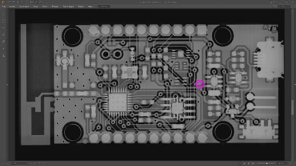
Things get interesting once he gets the module under the microscope and into the X-ray machine, but really interesting once the RF ASIC is uncapped, at the 15:18 mark. The die shots of the silicon germanium chip are impressively clear, and the analysis of all the main circuit blocks — voltage-controlled oscillator, power amps, mixer,  LNAs — is clear and understandable. For our money, though, the best part is the look at the VCO circuit, which appears to use a bank of fuses to tune the tank inductor and keep the radar within a tight 250-Mz bandwidth, for regulatory reasons. We’d love to know more about the process used in the factory to do that bit.

This isn’t [Shahriar]’s first foray into automotive radar, of course — he looked at a 77-GHz FMCW car radar a while back. That one was bizarrely complicated, though, so there’s something more approachable about a commodity product like this.

Continue reading “Take A Deep Dive Into A Commodity Automotive Radar Chip”

ImHex: An Open Hex Editor For The Modern Hacker

It’s little surprise that most hackers have a favorite text editor, since we tend to spend quite a bit of time staring at the thing. From writing code to reading config files, the hacker’s world is filled with seemingly infinite lines of ASCII. Comparatively, while a hex editor is a critical tool to have in your arsenal, many of us don’t use one often enough to have a clear favorite.

But we think that might change once you’ve taken ImHex for a spin. Developer [WerWolv] bills it specifically as the hex editor of choice for reverse engineering, it’s released under the GPL v2, and runs on Windows, Linux, and macOS. Oh, and did we mention it defaults to a slick dark theme designed to be easy on the eyes during those late night hacking sessions — just like your favorite website? Continue reading “ImHex: An Open Hex Editor For The Modern Hacker”

Reverse Engineering Saves Weller With A Wonky LCD From The Trash Pile

There’s nothing more satisfying than finding a broken piece of gear in the trash and bringing it back to life. Satisfying, but also potentially more time-consuming — someone tossed it for a reason, after all. Figuring out what that reason is and finding a way to back it better is where the fun — and the peril — are.

Luckily, some pieces of equipment have a relatively short list of well-known failure modes, a fact that [Lauri Pirttiaho] relied on for this fix of an old Weller WD1 soldering station. The unit, sporting the familiar light blue Weller livery and more than a few scratches and dings, had an LCD that was DOA. Typically it’s the driver that’s the problem here, but [Lauri]’s diagnosis revealed it was the LCD module itself that was bad.

With OEM replacements being basically unobtainium at this point, the fix was to intercept the data heading from the driver to the old LCD and send it to a new, easily sourced 16×2 character LCD display. This began with an inspection of the display controller’s datasheet, and a bit of probing of the old display to find out which segments and backplanes map to which pins. A little bit of case modding allowed the new display to fit, the old controller chip was removed, and a PIC16 went into its place, in a tidy nest of Kapton tape and bodge wires. The PIC does the job of translating the original display, which had a fair number of custom icons and symbols, into sensible text-based equivalents and sending them to the 16×2 via I2C. The video below shows the hack in action; it honestly looks like it could have come from the factory like that.

The nice thing here is that [Lauri]’s fix applies to a whole range of Weller stations, so if you find one in the trash, you might be able to resuscitate it. Failing that, you could always roll your own Weller from (more-or-less) scratch.

Continue reading “Reverse Engineering Saves Weller With A Wonky LCD From The Trash Pile”