AI Kayak Controller Lets The Paddle Show The Way

Controlling an e-bike is pretty straightforward. If you want to just let it rip, it’s a no-brainer — or rather, a one-thumber, as a thumb throttle is the way to go. Or, if you’re still looking for a bit of the experience of riding a bike, sensing when the pedals are turning and giving the rider a boost with the motor is a good option.

But what if your e-conveyance is more of the aquatic variety? That’s an interface design problem of a different color, as [Braden Sunwold] has discovered with his DIY e-kayak. We’ve detailed his work on this already, but for a short recap, his goal is to create an electric assist for his inflatable kayak, to give you a boost when you need it without taking away from the experience of kayaking. To that end, he used the motor and propeller from a hydrofoil to provide the needed thrust, while puzzling through the problem of building an unobtrusive yet flexible controller for the motor.

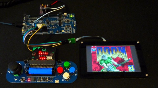
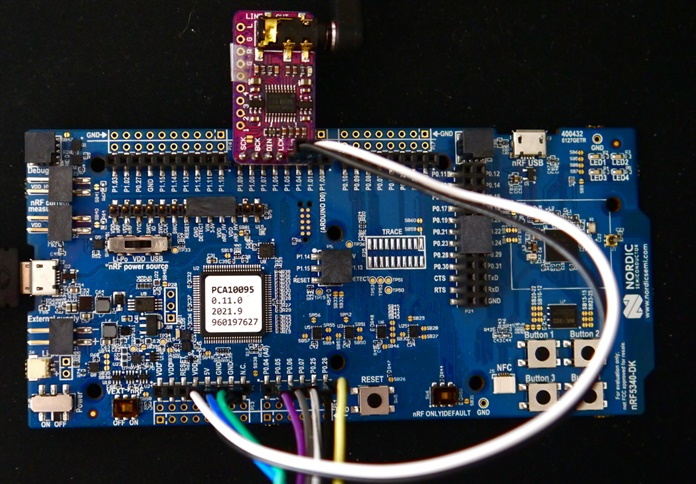
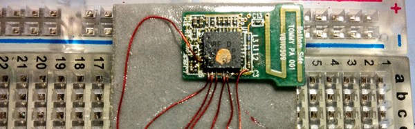
His answer is to mount an inertial measurement unit (IMU) in a waterproof container that can clamp to the kayak paddle. The controller is battery-powered and uses an nRF link to talk to a Raspberry Pi in the kayak’s waterproof electronics box. The sensor also has an LED ring light to provide feedback to the pilot. The controller is set up to support both a manual mode, which just turns on the motor and turns the kayak into a (low) power boat, and an automatic mode, which detects when the pilot is paddling and provides a little thrust in the desired direction of travel.

The video below shows the non-trivial amount of effort [Braden] and his project partner [Jordan] put into making the waterproof enclosure for the controller. The clamp is particularly interesting, especially since it has to keep the sensor properly oriented on the paddle. [Braden] is working on a machine-learning method to analyze paddle motions to discern what the pilot is doing and where the kayak goes. Once he has that model built, it should be time to hit the water and see what this thing can do. We’re eager to see the results.
Continue reading “AI Kayak Controller Lets The Paddle Show The Way”

Reverse Engineering Reveals Hidden API In Abandonware Trail Camera

It sometimes seems like there are two kinds of cheap hardware devices: those dependent on proprietary software that is no longer available and those that are equally dependent but haven’t been abandoned just quite yet. But rest assured, abandonment is always on the table, and until then, you get to deal with poorly written apps that often suffer from a crippling lack of essential functionality.

Such was the case for the wireless game camera that [Chris Jones] scored on the cheap, but rather than suffering with the original software, he decided to reverse engineer the camera and turn it into something more useful. The eBay description was promising — Bluetooth LE! WiFi! — but the reality proved less so. To save the batteries, WiFi is off by default and can only be turned on by connecting to the camera via BLE using a janky and crash-prone Android app.

[Chris]’ first step in reverse engineering the camera was to snoop into the BLE by capturing the Bluetooth packets to a file and running them through Wireshark. This revealed a write command with the text “BT_KEY_ON” — very promising. After verifying that this command turned on the camera’s access point, [Chris] got to work capturing WiFi packets using PCAPDroid and analyzing the results, again with Wireshark. Using every function available in the OEM app eventually revealed the full API on the camera, which gives file system control, access to individual images, and even putting the camera into live video mode.

Continue reading “Reverse Engineering Reveals Hidden API In Abandonware Trail Camera”

iPhone pictured with a lock

Make Your Own BLE-Enabled IOS App From Scratch

Even those readers who are most skeptical of Apple products will like this Bluetooth Low Energy (BLE)-enabled iOS app tutorial from [Akio].

With everything being “connected” these days smartphone applications are of course a ubiquitous part of our existence. We’ve seen plenty of examples connecting your Bluetooth-enabled projects to an Android device, but comparatively fewer tutorials for connecting to iOS devices. This mostly has to do with Android’s much larger market share and also Android’s more open-source friendly business model. Nevertheless, if you do much IoT development either as a hobby or professionally, then you probably find yourself interacting with Apple devices more than you like to admit.

[Akio’s] app is essentially updating a chart, in real-time, with data read from an Adafruit nRF52832 Feather board. He then walks you through all the basics of creating a user interface (UI) using Apple’s Storyboard interface, a simple drag-and-drop scheme similar to something you’ve probably used in many other contexts. [Akio] shows readers how to add buttons for allowing users to interact with the app, labels for displaying data to the user, as well as walks you through Apple’s odd methodology of connecting UI elements to code using IBAction and IBOutlets. The highlight of his tutorial is showing readers how to add charts to their iOS apps which seems to take a few more steps than you might imagine.

[Akio] does a really good job detailing all the relevant functions so that readers will hopefully understand what each piece of the code is doing. And we really enjoyed him adding individual video tutorials for some of the trickier programming steps. He also readily admits that some folks may opt to develop their UI exclusively in code as opposed to the Storyboard but he argues that the Storyboard is still important for beginners and is really handy when the UI is fairly simple.

Of course, in true open-source fashion, [Akio] provides all his code on his GitHub repository so you can clone the repo and run the code yourself as well as credit some of the resources he used while making his app. Two things we really love to see. Hopefully, [Akio’s] tutorial will make connecting to iOS devices seem much less onerous than it once was.

DOOM Comes To The NRF5340

If you’re looking for a reminder of how powerful the tiny microcontrollers that run our everyday gadgets have become, check out the work impressive work [Audun Wilhelmsen] has done to get DOOM running on the Nordic Semiconductor nRF5340. This is the sort of Bluetooth SoC you’d expect to find in a headset or wireless keyboard, and yet it’s packing a 128 MHz processor that can go head to head with the Intel 486 that the iconic first person shooter recommended you have in your old beige box PC.

That said, porting the open source shooter over to the nRF5340 wasn’t exactly easy. The challenge was getting the game, which recommended your PC have 8 MB back in 1993, to run on a microcontroller with a paltry 512 KB of memory. Luckily, a lot of the data the game loads into RAM is static. While that might have been necessary when the game was running from a pokey IDE hard drive, the nearly instantaneous access times of solid state storage and the nRF5340’s execute in place (XIP) capability meant [Audun] could move all of that over to an SPI-connected 8 MB flash chip with some tweaks to the code.

nRF53 Development board with I2S DAC

In general, [Audun] explains that many of the design decisions made for the original DOOM engine were made with the assumption that the limiting factor would be CPU power rather than RAM. So that lead to things often getting pre-calculated and stored in memory for instant access. But with the extra horsepower of the nRF5340, it was often helpful to flip this dynamic over and reverse the optimizations made by the original developers.

On the hardware side, things are relatively straightforward. The 4.3″ 800×480 LCD display is connected over SPI, and an I2S DAC handles the sound. Bluetooth would have been the logical choice for the controls, but to keep things simple, [Audun] ended up using a BBC micro:bit that could communicate with the nRF5340 via Nordic’s own proprietary protocol. Though he does note that Bluetooth mouse and keyboard support is something he’d like to implement eventually.

If some of the software tricks employed by this hack sounded familiar, it’s because a very similar technique was used to get DOOM running on an IKEA TRÅDFRI light bulb a week or so back. Unfortunately it must have ruffled some feathers, as it was pulled from the Internet in short order. It sounds like [Audun] got the OK from his bosses at Nordic Semiconductor to go public with this project, so hopefully this one will stick around for awhile.

Continue reading “DOOM Comes To The NRF5340”

A Smart Bandage For Monitoring Chronic Wounds

Here at Hackaday, we’re always enthralled by cool biohacks and sensor development that enable us to better study and analyze the human body. We often find ourselves perusing Google Scholar and PubMed to find the coolest projects even if it means going back in time a year or two. It was one of those scholarly excursions that brought us to this nifty smart bandage for monitoring wound healing by the engineers of FlexiLab at Purdue University. The device uses an omniphobic (hydrophobic and oleophobic) paper-based substrate coupled with an onboard impedance analyzer (AD5933), an electrochemical sensor (the same type of sensor in glucometers) for measuring uric acid and pH (LMP91000), and a 2.4 GHz antenna for wirelessly transmitting the data (nRF24L01). All this is programmed with an Arduino Nano. They even released their source code.

To detect uric acid, they used the enzyme uricase, which is very specific to uric acid and exhibits low cross-reactivity with other compounds. They drop cast uric acid onto a silver/silver chloride electrode printed on the omniphobic paper. Similarly, to detect pH, they drop cast a pH-responsive polymer called polyaniline emeraldine salt (PANI-ES) between two separate silver/silver chloride electrodes. All that was left was to attach the electrodes to the LMP91000, do a bit of programming, and there they were with their own electrochemical sensor. The impedance analyzer was a bit simpler to develop, simply attaching un-modified electrodes to the AD5933 and placing the electrodes on the wound.

The authors noted that the device uses a much simpler manufacturing process compared to smart bandages published by other academics, being compatible with large-scale manufacturing techniques such as roll-to-roll printing. Overcoming manufacturing hurdles is a critical step in getting your idea into the hands of consumers. Though they have a long way to go, FlexiLab appears to be on the right track. We’ll check back in every so often to see what they’re up to.

Until then, take a look at some other electric bandage projects on Hackaday or even make your own electrochemical sensor.

The Ifs Make Learning To Code Child’s Play

Anyone who has done the slightest bit of programming knows about the “Hello, World!” program. It’s the archetypal program that one enters to get a feel for a new language or a new architecture; if you can get a machine to print “Hello, World!” back to you, the rest is just details. But what about teaching kids to program? How does one get toddlers thinking in logical, procedural ways? More particularly, what’s a “Hello, World!” program look like for the pre-literate set?

Those are the sort of questions that led to The Ifs by [Makeroni Labs]. The Ifs are educational toys for teaching kids as young as three the basics of coding. Each If is a colorful plastic cube with a cartoon face and a “personality” that reflects what the block does – some blocks have actuators, some have sensors. The blocks are programmed by placing magnetic tabs on the top representing conditions and actions. A kid might choose to program a block to detect when it’s being shaken, or when the lights come on, and then respond by playing a sound or vibrating. The blocks can communicate with each other too, so that when the condition for one block is satisfied, something happens on another block.

The Ifs look like a lot of fun, and they’re a great jumpstart on the logical thinking skills needed for coders and non-coders alike. We’re not alone in thinking this is a pretty keen project – the judges for this year’s Hackaday Prize selected The Ifs as one of the twenty finalists. Will it win? We’ll find out next week at the 2019 Hackaday Superconference. If you won’t be in Pasadena with us, make sure you tune in to the livestream to watch the announcement.

Controlling Quadcopters With Wireless Mouse Dongles

Last week we gave away a few Crazyflie 2.0 quadcopters to some cool Hackaday Prize entries. This quadcopter ships with the intention of being controlled by your smartphone. But it can also be controlled by a PC with USB dongle and an nRF24LU1+ SOC. [ajlitt] didn’t figure out he wanted the USB dongle (the Crazyradio) that can control this quad until after he used his gift code to claim his Crazyflie quad. No matter; the dongles for Logitech wireless keyboards and mice use the same radio as the Crazyflie and can be modded to make this quad fly.

The board inside the Logitech unifying receiver is a simple affair, with some pads for the USB connector, a crystal, the nRF24LU1+ radio module, and a few passives. To get this radio chip working with his computer, [ajlitt] simply needed to break out the SPI pins and wire everything to a Bus Pirate.

Getting the Crazyradio firmware onto this proved to be a little harder than soldering some magnet wire onto a few pins. The chip was first flashed without a bootloader, a full image with the bootloader was found, after wrangling a single byte into place, [ajlitt] had a working Crazyflie radio made from a wireless mouse dongle. The range isn’t great  – only 30 feet or so, or about as far as you would expect a wireless mouse to work. Excellent work, even if [ajlitt] is temporarily without a mouse.

The Crazyflie 2.0 is available from the Hackaday Store, along with the add-ons if you don’t want to hack your own.