Android And Arduino RF Outlet Selector

ardAndRFoutlets

Cyber Monday may be behind us, but there are always some hackable, inexpensive electronics to be had. [Stephen’s] wireless Android/Arduino outlet hack may be the perfect holiday project on the cheap, especially considering you can once again snag the right remote controlled outlets from Home Depot. This project is similar to other remote control outlet builds we’ve seen here, but for around $6 per outlet: a tough price to beat.

[Stephen] Frankenstein’d an inexpensive RF device from Amazon into his build, hooking the Arduino up to the 4 pins on the transmitter. The first step was to reverse engineer the communication for the outlet, which was accomplished through some down and dirty Arduino logic analyzing. The final circuit included a standard Arduino Ethernet shield, which [Stephen] hooked up to his router and configured to run as a web server. Most of the code was borrowed from the RC-Switch outlet project, but the protocols from that build are based on US standards and did not quite fit [Stephen’s] needs, so he turned to a similar Instructables project to work out the finer details.

Stick around after the break for a quick video demonstration, then check out another wireless outlet hack for inspiration.

Continue reading “Android And Arduino RF Outlet Selector”

Repairing And Adding Bluetooth Control To An Induction Cooker

When his 6 years old induction cooker recently broke, [Johannes] decided to open it in an attempt to give it another life. Not only did he succeed, but he also added Bluetooth connectivity to the cooker. The repair part was actually pretty straight forward, as in most cases the IGBTs and rectifiers are the first components to break due to stress imposed on them. Following advice from a Swedish forum, [Johannes] just had to measure the resistance of these components to discover that the broken ones were behaving like open circuits.

He then started to reverse engineer the boards present in the cooker, more particularly the link between the ‘keyboards’ and the main microcontroller (an ATMEGA32L) in charge of commanding the power boards. With a Bus Pirate, [Johannes] had a look at the UART protocol that was used but it seems it was a bit too complex. He then opted for an IOIO and a few transistors to emulate key presses, allowing him to use his phone to control the cooker (via USB or BT). While he was at it, he even added a temperature sensor.

Reverse Engineering The Sony Ericsson Vivaz High Resolution 640 X 360 Cellphone LCD

In our opinion, reverse engineering may be one of the best ways to tease your brain. [Andy] just did that by reverse engineering the Sony Ericsson Vivaz high resolution LCD (cached copy here). In his (very) nicely written article, [Andy] explains all the steps that led him to the result shown in the picture above. He started by finding the repair manual of the Vivaz, to discover that the display could be interfaced with 8080 type parallel signals. That meant that he could use a standard microcontroller without high speed buses to interface with it, in this case the STM32F4. Next in his adventure, [Andy] ordered the appropriate connector and took a more educated guess for the onboard microcontroller. A long Google search brought up the R61523 from Renesas. So he designed his breakout board, got it produced and a few hours later a nice picture was being shown on the LCD. He even took the time to compare the original display with the clone he found on the webs, and modified his graphics library to support this display.

Hacking A Flip Dot Display

While casually lurking on a famous auction website, [TeddyDesTodes] found the gem shown in the above picture and reverse engineered it. This is a flip dot display, the Brose Vollmatrix compact to be precise. It consists of a grid of small metal discs that are black on one side and yellow on the other, set into a black background. With power applied, the disc flips to show the other side. The disc is attached to an axle which also carries a small permanent magnet. Positioned close to the magnet is a solenoid. By pulsing the solenoid coil with the appropriate electrical polarity, the magnet will align itself with the magnetic field, also turning the disc.

After carrying the 25kg display from his post office to home, [TeddyDesTodes] opened it and discovered that the main control board was using two RS422 transceivers. So he fired up his bus pirate, started to sniff the traffic and noticed that several commands were repeatedly sent. [TeddyDesTodes] stopped the transmission, sent these particular commands and had the good surprise to see some dots flipped. From there, displaying something was a piece of cake.

If this is familiar to you it may be because it was shared in one of the Trinket Contest Updates. But the background details were just so much fun we think this deserves a full feature of it’s own. Do you agree?

[Ken Shirriff] Completely Reverse Engineers The 1974 Sinclair Scientific Calculator

Wow. Seriously… Wow! The work [Ken Shirriff] put into reverse engineering the Sinclair Scientific is just amazing. He covers so much; the market forces that led [Clive Sinclair] to design the device with an under-powered chip, how the code actually fits in a minuscule amount of space, and an in-depth look at the silicon itself. Stop what you’re doing and read it right now!

This calculator shoe-horned itself into the market when the HP-35 was king at a sticker price of $395 (around $1800 in today’s money). The goal was to undercut them, a target that was reached with a $120 launch price. They managed this by using a Texas Instruments chip that had only three storage registers, paired with a ROM totaling 320 words. The calculator worked, but it was slow and inaccurate. Want to see how inaccurate? Included in the write-up is a browser-based simulator built from the reverse engineering work. Give it a try and let us know what you think.

Now [Ken] didn’t do all this work on his own. Scroll down to the bottom of his post to see the long list of contributors that helped bring this fantastic piece together. Thanks everyone!

[Thanks Ed]


Reverse-engineering Old Finnish Metro Station Displays

This project definitely was a patience tester. As the control system of the Helsinki metro was (and still is) under big renovation, [Konsta] could buy three old information displays for a very cheap price (5€ each). However, these displays came with no information whatsoever about the way to drive them, thus starting a long reverse-engineering journey.

[Konsta] started by taking one apart, discovering that each side of the display was composed of 10 daisy-chained LCD screens and some kind of control box. As you may have guessed, the key to reverse engineering the display was studying the contents of this box. It turned out that the control electronics were composed of an 8085 CPU, some RAM, a peripheral I/O chip, an UV-erasable EPROM chip (containing 32KB of program memory) and an EEPROM.

[Konsta] used an AVR to dump the memory contents of the two latter chips and it was at this part of the project that the Helsinki Hacklab joined in. Together, they reverse engineered the control PCB, studied the assembler code, sniffed the different on-board buses to fully understand how the display could be controlled.

We strongly recommend reading [Konsta]’s writeup, especially knowing that he made this english page just for us!

Reverse Engineering A Wireless Protocol

logic

Like all good tinkerers, [Andrew] decided to figure out how his wireless security system worked. Yes, it’s an exercise in reverse engineering, and one of the best we’ve seen to date.

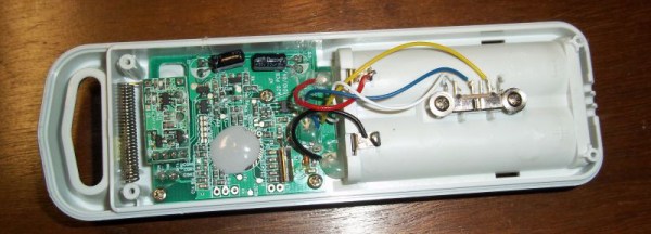
After breaking out the handheld spectrum analyzer and TV tuner SDR, [Andrew] cracked open a few devices and had a gander at the circuit boards. The keypad, PIR sensor, and base station all used a TI radio chip – the CC11xx series – that uses SPI to communicate with a microcontroller.

Attaching a logic analyzer directly to the radio chip and reading the bits directly, [Andrew] started getting some very good, if hard to understand data. From the security system specs, he knew it used a ’20-bit code’, but the packets he was reading off the SPI bus were 48 bits long. The part of this code was probably the system’s address, but how exactly does the system read its sensors?

The easiest way to figure this out was to toggle a few of the sensors and look at the data being transmitted. With a good bit of reasoning, [Andrew] figured out how the alarm system’s code worked. This theory was tested by connecting one of the radios up to an Arduino and having his suspicions confirmed.

While [Andrew]’s adventure in reverse engineering is only a benefit for people with this model of security system, it’s a wonderful insight into how to tear things apart and understand them.