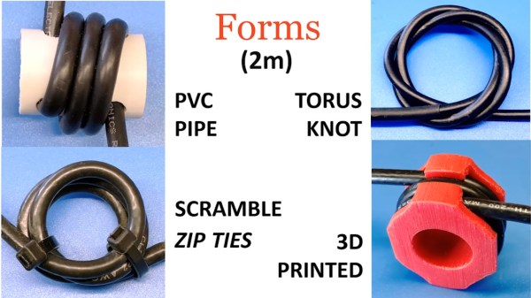
Introducing FISSURE: A Toolbox For The RF Hacker

No matter what the job at hand is, if you’re going to tackle it, you’re going to need the right kit of tools. And if your job includes making sense out of any of the signals in the virtual soup of RF energy we all live in, then you’re going to need something like the FISSURE RF framework.

Exactly what FISSURE is is pretty clear from its acronym, which stands for Frequency Independent SDR-Based Signal Understanding and Reverse Engineering. This is all pretty new — it looks like [Chris Poore] presented a talk at DEFCON a few weeks back about using FISSURE to analyze powerline communications between semi-trucks and their trailers, and they’ve got a talk scheduled for next month’s GNU Radio Conference as well. We’ve been looking through all the material we can find on FISSURE, and it appears to be an RF hacker’s dream come true. They’ve got a few examples on Twitter, like brute-forcing an old garage door opener with a security code set by a ten-position DIP switch, and sending tire pressure monitoring system (TPMS) signals to a car. They also mention some of the framework’s capabilities on the GitHub README; we’re especially interested in packet crafting for various protocols. The video below has some more examples of what FISSURE can do.

It looks like FISSURE could be a lot of fun, and very handy for your RF analysis and reverse engineering work. If you’ve been using Universal Radio Hacker like we have, this looks similar, only more so. We’ll be downloading it soon and giving it a try, so be on the lookout for a hands-on report.

Continue reading “Introducing FISSURE: A Toolbox For The RF Hacker”

SATAn Turns Hard Drive Cable Into Antenna To Defeat Air-Gapped Security

It seems like [Mordechai Guri]’s lab at Ben-Gurion University is the place where air-gapped computers go to die, or at least to give up their secrets. And this hack using a computer’s SATA cable as an antenna to exfiltrate data is another example of just how many side-channel attacks the typical PC makes available.

The exploit, deliciously designated “SATAn,” relies on the fact that the SATA 3.0 interface used in many computers has a bandwidth of 6.0 Gb/s, meaning that manipulating the computer’s IO would make it possible to transmit data from an air-gapped machine at around 6 GHz. It’s a complicated exploit, of course, and involves placing a transmitting program on the target machine using the usual methods, such as phishing or zero-day exploits. Once in place, the transmitting program uses a combination of read and write operations on the SATA disk to generate RF signals that encode the data to be exfiltrated, with the data lines inside the SATA cable acting as antennae.

SATAn is shown in action in the video below. It takes a while to transmit just a few bytes of data, and the range is less than a meter, but that could be enough for the exploit to succeed. The test setup uses an SDR — specifically, an ADALM PLUTO — and a laptop, but you can easily imagine a much smaller package being built for a stealthy walk-by style attack. [Mordechai] also offers a potential countermeasure for SATAn, which basically thrashes the hard drive to generate RF noise to mask any generated signals.

While probably limited in its practical applications, SATAn is an interesting side-channel attack to add to [Dr. Guri]’s list of exploits. From optical exfiltration using security cameras to turning power supplies into speakers, the vulnerabilities just keep piling up.

Continue reading “SATAn Turns Hard Drive Cable Into Antenna To Defeat Air-Gapped Security”

A Receive Antenna Switcher With An Espressif Brain

It’s not uncommon for a radio enthusiast to have multiple antennas for the same radio, so as you might expect it’s also entirely usual to have a bunch of coaxial cables dangling down for fumbling around the back of the rig to swap over.  If that describes your radio experience than you might be interested in the antenna switcher built by [g3gg0], which uses solid-state RF switches controlled by an ESP32 module.

At its heart is the MXD8625C RF switch, a tiny device designed for cellular phone applications that delivers only a fraction of a dB insertion loss and somehow negates the need for any blocking capacitors. It’s controlled by a GPIO line, and he’s hooked up a brace of them to allow the distribution of three antennas to a couple of radios with the handy option of switching in a preamplifier if required. Of even more interest we note that the device is suitable for transmitter switching too, with a maximum 36.5 dBm throughput that we calculate to be about 4.5 W. This board is fairly obviously for receive use, but perhaps the chip is of interest to anyone considering a transceiver project. Meanwhile the software is a relatively simple web-based control linking on-screen controls to GPIOs.

If you are interested in solid state RF switches, it’s always worth remembering that at lower frequencies they can be very simple indeed.

A FET Oscilloscope Probe For Higher Frequencies

It’s a problem that has dogged electronic engineers since the first electrons were coaxed along a wire: that measuring instruments can themselves disrupt the operation of a circuit. Older multimeters for example had impedances low enough to pull resistor values, thus our multimeters today have high-impedance FET inputs. [Christoph] faced it with his oscilloscope probe, its input capacitance was high enough to put unacceptable load on a crystal oscillator and stop it oscillating. He thus built a FET input probe for higher RF frequencies, and its construction is an accessible view of wideband RF instrumentation design.

The circuit is a very simple one using a dual-gate FET, but the interest comes in the PCB and screening can design to ensure good RF performance. Off-the-shelf cans have four sides, so to accommodate the circuit one wall of the can had to be removed. The end result is a tiny PCB with miniature co-ax connectors for power and signal, which when characterised was found to have a 1.3 GHz bandwidth and a very low input capacitance.

If the language of RF design is foreign to you, may we recommend [Michael Ossmann]’s talk at a Superconference a few years ago.

IR Remote Transforms To RF

Most consumer remote controls operate using infrared light. This works well assuming the piece of equipment has a line of sight to the remote. But if you have, say a receiver in a cabinet or closet, the IR remote signal can’t reach the sensor. Some equipment has remote receivers that you can leave poking out, but it is still not very handy. That’s why some equipment now uses RF remotes. [Xtropie] used a pair of inexpensive 433 MHz RF modules to convert an IR system to RF. You can see a short video about the project below.

We might have been tempted to simply put an IR LED on the receiver so it could feed IR into the device sensor, but [Xtropie] took a different approach. He found the IR sensor and tied the RF receiver directly into its output. It seems to work, but we probably would have removed the IR sensor to make sure there were no conflicts.

Continue reading “IR Remote Transforms To RF”

Impedance Matching Revisited

If you are an old hand at RF design, you probably have a good handle on matching impedance. However, if you are just getting started with RF, [FesZ Electronic]’s latest video series on lossless impedance matching is well worth watching.

Matching is important for several reasons. Maximum power transfer occurs when the source and load impedance match. Also, at RF, mismatched impedance can cause reflections which, again, robs you of useful power. The video covers some math and then moves on to LTSpice to simulate a test circuit. But the part you are really waiting for — the practical circuits — is about 15 minutes in. Since the values you need are often oddball, [FesZ] makes his own adjustable inductors and uses a trimmer capacitor to adjust the actual capacitance value.

This is a big topic, but the first video is a great introduction blending theory, simulation, and hands-on. A great way to get started with a very fundamental RF design skill.

We’ve worked on explaining all this before if you want a second take on it. If you want to understand why mismatched impedance leads to less power delivery, we’ve done that, too.

Continue reading “Impedance Matching Revisited”

NFC Performance: It’s All In The Antenna

NFC tags are a frequent target for experimentation, whether simply by using an app on a mobile phone to interrogate or write to tags, by incorporating them in projects by means of an off-the-shelf module, or by designing a project using them from scratch. Yet they’re not always easy to get right, and can often give disappointing results. This article will attempt to demystify what is probably the most likely avenue for an NFC project to have poor performance, the pickup coil antenna in the reader itself.

A selection of the NFC tags on my desk

The tags contain chips that are energised through the RF field that provides enough power for them to start up, at which point they can communicate with a host computer for whatever their purpose is.

“NFC” stands for “Near Field Communication”, in which data can be exchanged between physically proximate devices without their being physically connected.  Both reader and tag achieve this through an antenna, which takes the form of a flat coil and a capacitor that together make a resonant tuned circuit. The reader sends out pulses of RF which is maintained once an answer is received from a card, and thus communication can be established until the card is out of the reader’s range. Continue reading “NFC Performance: It’s All In The Antenna”