[Ben Katz] designed the original MIT Mini Cheetah robot, which easily captured attention and imagination with its decidedly un-robotic movements and backflips. Not long after [Ben]’s masters thesis went online, clones of the actuators started to show up at overseas sellers, and a few months after that, clones of the whole robot. [Ben] recently had the opportunity to disassemble just such a clone by Dogotix and see what was inside.

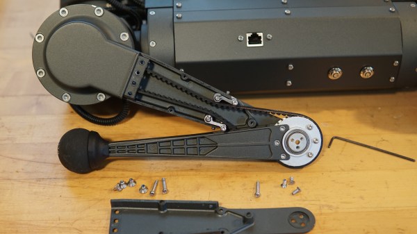
Amusingly, one of the first things he noticed is that the “feet” are still just off-the-shelf squash balls, same as his original mini cheetah design. As for the rest of the leg, inside is a belt that goes past some tensioners, connecting the knee joint to an actuator in the shoulder.
As one may expect, these parts are subject to a fair bit of stress, so they have to be sturdy. This design allows for slender yet strong legs without putting an actuator in the knee joint, and you may recall we’ve seen a similar robot gain the ability to stand with the addition of a rigid brace.
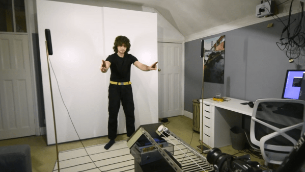
It’s interesting to read [Ben]’s thoughts as he disassembles and photographs the unit, and you’ll have to read his post to catch them all. But in the meantime, why not take a moment to see how a neighbor’s curious sheep react to the robot in the video embedded below? The robot botches a backflip due to a low battery, but the sheep seem suitably impressed anyway.
Continue reading “Mini Cheetah Clone Teardown, By None Other Than Original Designer”