Bargain Bin Barcode Scanner Keeps Track Of Shopping Needs

For most people, a Post-It note or dry-erase board suffices to ensure that household consumables are replenished when they’re used up. But hackers aren’t like most people, so this surplus barcode scanner turned kitchen inventory manager comes as little surprise. After all, if something is worth doing, it’s worth overdoing.

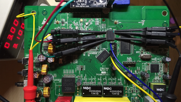
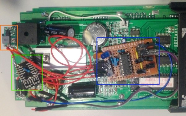
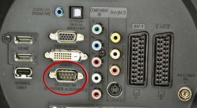
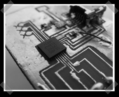
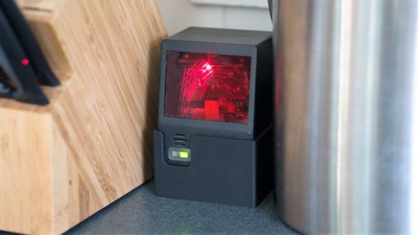
[Brian Carrigan]’s project began with a chance discovery of an old barcode scanner in his local scrap store. Questions as to why we can never find bargains like a $500 scanner for six bucks aside, [Brian] took the scanner home for a bit of reverse engineering. He knew it used RS-232 but it had been unceremoniously ripped from its connectors, so identifying pins took some detective work. With power and data worked out and the scanner talking to a Raspberry Pi, [Brian] set about integrating it into Wunderlist,  a cloud-based list management app. Now when someone eats the last Twinkie, a quick scan of the package looks up the product name via an API call to the UPC database and posts it to Wunderlist. And we’ll bet the red laser beams bouncing around the kitchen make a great nightlight too.

With smartphone barcode reading apps, this might seem a bit like overkill, but we like it just the same. And if barcodes leave you baffled, check out our introduction to these studies in black and white that adorn just about everything.

Dummies Guide To Reverse Engineering

[Juan Carlos Jiménez] has reverse engineered a router — specifically, a Huawei HG533. While that in itself may not sound substantial, what he has done is write a series of blog posts which can act as a great tutorial for anyone wanting to get started with sniffing hardware. Over the five part series, he walks through the details of identifying the hardware serial ports which open up the doors to the firmware and looking at what’s going on under the hood.

The first part deals with finding the one or several debug ports on the hardware and identifying the three important pins – Rx, Tx and GND. That’s when he shows novices his first trick – shining a flashlight from under the PCB to find the pins that have trace connections (most likely Rx and Tx), those that don’t have any connections (most likely CTS and DTR) and those that have connections to the copper pour planes (most likely VCC and GND). The Tx signal will be pulled up and transmitting data when the device is powered up, while the Rx signal will be floating, making it easy to identify them. Finding the Baud rate, though, will require either a logic analyser, or you’ll have to play a bit of a guessing game.

Once you have access to the serial port and know its baud rate, it’s time to hook it up to your computer and use any one of the several ways of looking at what’s coming out of there — minicom, PuTTY or TeraTerm, for example. With access to the devices CLI, and some luck with finding credentials to log in if required, things start getting interesting.

Over the next part, he discusses how to follow the data paths, in this case, looking at the SPI signals between the main processor and the flash memory, and explaining how to use the logic analyser effectively and decode the information it captures. Moving further, he shows how you can hook up a USB to SPI bridge, connect it to the flash memory, take a memory dump of the firmware and read the extracted data. He wraps it up by digging in to the firmware and trying to glean some useful information.

It’s a great series and the detailed analysis he does of this particular piece of hardware, along with providing a lot of general tips, makes it a perfect starting point for those who need some help when getting started on debugging hardware.

Thanks, [gnif] for posting this tip.

Continue reading “Dummies Guide To Reverse Engineering”

IoT-ifying An Old LED Signboard

Scrolling LED signs were pretty keen back in the day, and now they’re pretty easy to come by on the cheap. Getting a signboard configured for IoT duty can be tricky, but as [kripthor] shows us, it’s not that bad as long as security isn’t your top concern and you can tweak a serial interface.

dec-16-2016-10-57-pm-edited[kripthor] chanced upon an Amplus AM03127 signboard that hails from the days when tri-color LEDs were the big thing. The unit came with a defunct remote thanks to leaking batteries, but a built-in serial interface offered a way to connect. Unfortunately, the RS-232 standard on the signboard wants both positive and negative voltages with respect to ground to represent the 1s and 0s, and that wouldn’t work with the ESP8266 [kripthor] was targeting. The ubiquitous MAX-232 transceiver was enlisted to convert logic levels to RS-232 signals and a small buck converter was added to power the ESP. A little scripting and the signboard is online and ready for use and abuse by the interwebz — [kripthor] says he’ll regret this, but we’re pleased with the way the first remote access turned out. Feel free to check out the live video feed and see what the current message is.

Personally, we don’t have much use for a signboard, but getting RS-232 devices working in the Arduino ecosystem is definitely a trick we’ll keep in mind. If asynchronous serial protocols aren’t your strong suit, you might want to check out this guide to what can go wrong by our own [Elliot Williams].

Fixing A Multimeter’s Serial Interface

[Shane] bought a multimeter with the idea of using its serial output as a source for data logging. A multimeter with a serial port is a blessing, but it’s still RS-232 with bipolar voltage levels. Some modifications to the meter were required to get it working with a microcontroller, and a few bits of Python needed to be written, but [Shane] is getting useful data out of his meter.

The meter in question is a Tenma 72-7735, a lower end model that still somehow has an opto-isolated serial output. Converting the bipolar logic to TTL logic was as easy as desoldering the photodiode from the circuit and tapping the serial data out from that.

With normal logic levels, the only thing left to do was to figure out how to read the data the meter was sending. It’s a poorly documented system, but [Shane] was able to find some documentation for this meter. Having a meter output something sane, like the freaking numbers displayed on the meter would be far too simple for the designers of this tool. Instead, the serial port outputs the segments of the LCD displayed. It’s all described in a hard to read table, but [Shane] was able to whip up a little bit of Python to parse the serial stream.

It’s only a work in progress – [Shane] plans to do data logging with a microcontroller some time in the future, but at least now he has a complete understanding on how this meter works. He can read the data straight off the screen, and all the code to have a tiny micro parse this data.

Change The TV Channel Over IP

tv-channel-change-over-ip

[Mustafa Dur] wrote in to tell us about his hack to control the television with a smartphone. Now the one-IR-remote-to-rule-them hacks have been gaining popularity lately so we assumed that’s how he was doing it. We were wrong. He’s using his satellite receiver to provide the Internet connection. It pushes commands to his LG 47LH50 TV which has an RS-232 port.

The image above is the back of another LG television (it came from a forum post about controlling the TV with a PC). [Mustafa] is using a Dreambox DM800 satellite receiver which also has a serial port an he can telnet into it. He searched around the Internet and discovered that it should be possible to connect the two using a null modem cable. His initial tests resulted in no response, but a tweak to the com port settings of the box got his first command to shut off the television. After a bit of tweaking he was able to lock in reliable communications which he made persistent by writing his own startup script. From there he got to work on a Python script which works as the backend for a web-based control interface.

If you want to find out what else you can do with this type of serial connection read about this hack which used a script to try every possible command combination.

USB To RS-232 Adapter Hacked To Use RS485 Instead

[André Sarmento] needed to connect a computer to an RS-485 bus. A simple converter can be sourced online, but the only thing he could find locally that was even close was a USB to RS-232 converter. He used that component to craft his own USB to RS-485 bridge.

RS-485 is often used for remote sensors as it provides a method of connecting electronics over long distances. The converter which he started with seems to be encased in a hot-glue-like substance. A bit of time with a torch and he was able to get to the components on the board. There are two stages, one which converts RS-232 to TTL, and the other converts TTL to USB. [André] removed the RS-232 chip and patched his own board (shown on the left) into its TTL lines. He was also able to add a few more configuration options, like using an external power source, and having a few jumper-selected resistor options.

RS-232 USB Madness


If you’ve been amused by the lengths people go through to speak to a serial device these days. [timmeh] just took the cake. He build his own frikkin’ tiny RS-232 to USB interface with the diminutive SIL CP2101. The package on it is QFN-28 (If PLCC is Darth Vader, QFN-28 is his mean little brother.) That said, if you prefer to work with stuff that talks TTL or RS-232, this could be a handy add-on to pop a USB port on your project. (Oh, look, they have samples…) Sure, we’ve beaten the serial connections to death, but they’re so handy we just can’t resist. It may be a decent way to add a serial port to your laptop. (Picture this: dell’s bluetooth cards are usb devices – you could add one of these without even voiding your warranty.)