Screenshot of the cheatsheet being developed in Inkscape

Improve Your KiCad Productivity With These Considered Shortcut Keys

[Pat Deegan] from Psychogenic Technologies shows us two KiCad tips to save a million clicks, and he made a video to support it, embedded below.

In the same way that it makes sense for you to learn to touch type if you’re going to be using a computer a lot, it makes sense for you to put some thought and effort into your KiCad keyboard shortcuts keys, too.

In this video [Pat] introduces the keymap that he has come up with for the KiCad programs (schematic capture and PCB layout) and explains the rules of thumb that he used to generate his recommended shortcut keys, being:

  • one handed operation; you should try to make sure that you can operate the keyboard with one hand so your other hand can stay on your mouse
  • proximity follows frequency; if you use it a lot it should be close to hand
  • same purpose, same place; across programs similar functions should share the same key
  • birds of a feather flock together; similar and related functionality kept in proximate clusters
  • typing trounces topography; if you have to use both hands for typing you have to take your hand off the mouse anyway so then it doesn’t really matter where on the keyboard the shortcut key is

You can find importable KiCad keymaps and customizable SVG cheatsheets in the downloads section.

[Pat]’s video includes some other tips and commentary, but for us the big takeaway was the keymaps. He’s also got a course that you can follow along with for free. And if you haven’t been keeping abreast of developments, KiCad is now at version 9, as of February this year.

Continue reading “Improve Your KiCad Productivity With These Considered Shortcut Keys”

KiCad 2022 Year End Recap

KiCad 2022 End-of-Year Recap And 7.0 Preview

[Chris Gammell] moderated the KiCad 2022 End-of-Year Recap with several KiCad developers and librarians. They reviewed what’s been bubbling up in the nightly KiCad 6 builds, what we can expect from KiCad 7, and even answered some questions from the user community. Over the course of 2022, the KiCad project has grown both its development team and library team. The project even has a preliminary support commitment from the CERN Drawing Office!

Improvements to the KiCad Schematic Editor include smart wire dragging that simplifies moving components around within schematic diagrams. Components selected in the schematic now remain selected while switching to the PCB Editor. Internal documentation of schematics has advanced with support for fonts, embedded graphics, and the inclusion of hypertext links to datasheets and other reference materials. New features for PDF generation offer interactive files and links between sheets.

A new search panel within the KiCad PCB Editor supports finding components by footprint, net, or text search. A property panel allows common properties to be edited across multiple selected items. While a full-blown auto-router remains outside of the scope for KiCad, “push and shove” routing is faster and easier. An “attempt to finish” feature routes a quick connection for the currently selected trace, and “pack and move” positions all selected footprints into proximity to simplify placing them as neighbors within the board layout.

The KiCad PCB Editor also adds support for the use of fonts and inverted “knockout text” which even works on copper zones. Bitmap graphics can be imported and scaled beneath layout work as reference illustrations. Private footprint layers can be used to place extra documentation within footprints. The design rule checker (DRC) now can catch more layout issues, especially those that may impact manufacturability.

These are just a sampling of the impressive improvements we can expect with KiCad 7.0. There are also additions to circuit simulation and modeling features, a new command line interface for script-based automation, ARM64 support for KiCad running on Apple silicon, and a huge number of additions to the default library including symbols, footprints, and 3D Viewer models.

The KiCad team suggests several ways to support the project. There are always needs for additional developers and librarians. Financial contributions can be made at kicad.org. As users, we can run the nightly builds, try to break them, and give feedback in the form of detailed bug reports. Community testing will help make KiCad 7.0 as solid as possible. The project team is also seeking open hardware projects to include with KiCad 7.0 as demos.  For example, the StickHub project was included with KiCad 6.0 as a demo.

The official release of KiCad 7.0 is currently scheduled for January 31, 2023. While we wait, let’s flashback to our January 2022 presentation of what features made it into the KiCad 6.0 release.

Continue reading “KiCad 2022 End-of-Year Recap And 7.0 Preview”

New Release Of FidoCadJ Draws Schematics Everywhere

Do you remember drawing your first schematic? Presumably you used a pen or a pencil and some kind of paper. Schematic capture software, though, makes it so much easier to draw schematics. There are many to choose from, but we spent some time checking out FidoCadJ and found it capable. Of course, there are many other options, but we did like that FidoCadJ runs locally and since it uses Java will run on just about any computer. Since it is open-source, you can modify it and you don’t have to worry about licensing it for your many computers or your team.

The program is a JAR file, and our first attempt to run it ran afoul of our older Java version that was the default Java Runtime Environment. But that was easy to fix, especially since a newer version was there, just not the default.

Continue reading “New Release Of FidoCadJ Draws Schematics Everywhere”

Ask Hackaday: How Do You Draw Schematics?

The lingua franca of electronic design is the schematic. I can pick up a datasheet written in Chinese (a language I do not read or speak) and usually get a half-decent idea of what the part is all about from the drawings. Unfortunately, even as my design experience has grown over the years, I haven’t quite learned to think in schematics — I need to see it on paper (or on a screen) to analyze a circuit. Whether it’s literally on the back of an envelope or sketched in the condensation on the shower stall, actually drawing a design or idea makes a huge difference in being able to understand it. And, if you’ve ever tried to explain a circuit without a schematic — in an on-line forum or over the phone, for instance — you know how difficult it is.

So, given the importance of the schematic for design and communication, you’d think choosing a tool to draw them would be an easy task. Not so. There are dozens of choices, from dedicated schematic drawing programs to using the schematic-capture facilities of simulation or PCB design tools, or even old-fashioned pencil-and-paper and its modern equivalents. Each one has its pros and cons, and may be better suited to one specific application, but you have to choose something.

So, readers of Hackaday, what do you use to convey your electronic design ideas to the world?

Continue reading “Ask Hackaday: How Do You Draw Schematics?”

Automagic Tool Makes KiCAD Schematic Symbols From PDFs

Last time we talked about a KiCAD tool it was to describe a way to make the zen-like task of manual assembly more convenient. But what about that most onerous of EE CAD tasks, part creation? Home makers probably don’t have access to expensive part library subscriptions or teams of people to create parts for them, so they are left to the tedium of creating them by hand. What if the dream tool existed that could read the darn PDF by itself and make a part? It turns out [Sébastien] made that tool and it’s called uConfig.

uConfig has a pretty simple premise. It scrapes manufacturer datasheets in PDF form, finds what it thinks are diagrams of parts with pin names, functions, etc, and emits the result as parts in a KiCAD library. To aid in the final conversion [Sébastien] added rules engine which consume his custom KiCAD Style Sheets which specify how to categorize pins. In the simple case the engine can string match or use regex to let you specify things like “all pins named VDD[A-C] should be power pins”. But it can also be used to move everything it thinks belongs to “GPIOB” and stick them on the bottom of the created symbol. We could imagine features like that would be of particular use breaking out gigantic parts like a 400 ball BeagleBone on a chip.

Thanks for the tip [arturo182]!

KiCad Utilities Generate Parts; Track Costs

The popularity of KiCad keeps increasing, and not only are more people converting to it and using it for their projects, but there’s also a growing number of folks actively contributing to the project in the form of libraries, scripts and utilities to improve the work flow.

KiPart

[Dave Vandenbout] a.k.a [xesscorp] has written a couple of utilities for KiCad. When working with large multi pin parts such as micro-controllers, creating a schematic symbol from scratch using the traditional KiCad schematic library editor can be quite tedious. KiPart is a python script that uses a CSV table as its input to generate the KiCad schematic symbol and is able to create multi-part symbols too. Usage is quite simple. The csv file needs a part name on its first row. The next row contains the headers. ‘Pin’ number and Pin ‘Name’ are the minimum required. Additionally, you can add in ‘Unit’, ‘Side’, ‘Type’, and ‘Style’. Unit is used when defining multi-unit parts. Side decides the location of the pin, Type its function, and Style is its graphic representation. Running the KiPart python script then results in a nice KiCad schematic symbol. Besides, KiPart can specifically generate schematic symbols for the Xilinx 7-Series FPGAs and the Cypress PSoC5LP. There are a whole host of options to customize the final output, for example ordering pin placement based on pin number, or pin name or pin function. Source files can be obtained from the [xesscorp] Github repository.

KiCost

KiCost
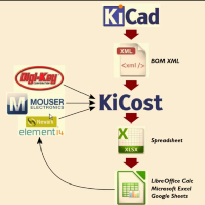
Another useful utility from [xesscorp] is KiCost. It is intended to be run as a script for generating part-cost spreadsheets for circuit boards developed with KiCad. The one piece of information you need to add to your schematic parts is a manufacturers part number. The KiCost Python script then processes the BOM XML file, reading the manufacturer part number, scraping the web sites of several popular distributors for price and inventory data, and creating a costing spreadsheet. You can grab the source files from the KiCost Github repository.

Check the two videos below where [Dave] walks through the two utilities.

Thanks to [RoGeorge] for sending in this tip by commenting on the Open Source FPGA Pi Hat built by [Dave] that we featured recently.

Continue reading “KiCad Utilities Generate Parts; Track Costs”

The Worst CAD Package Ever Is Still Handy

A lot of great schematics wind up on the back of bar napkins or diner place mats. When inspiration strikes, you have to capture it, after all. Today, you are as likely to draw schematics on a computer and there are plenty of options for that; if you can install software your options are almost limitless. And if you have a modern Web browser, there are lots of good options that don’t even require an install.

But what about those times when you need a quick schematic to pop into a presentation? You are on some ancient conference room computer where you can’t install anything and it’s still running a browser that understands the <BLINK> tag? Try out the Klunky Schematic Editor. Your browser will need Javascript, but that’s about all. No HTML 5 or anything fancy.

Continue reading “The Worst CAD Package Ever Is Still Handy”