Circuit simulation and software workbooks like Matlab and Jupyter are great for being able to build things without a lot of overhead. But these all have some learning curve and often use clever tricks, abstractions, or library calls to obscure what’s really happening. Sometimes it is clearer to build math models in a spreadsheet.
You might think that spreadsheets aren’t built for doing frequency calculation and visualization but you’re wrong. That’s exactly what they’re made for — performing simple but repetative math and helping make sense of the results.
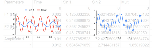
In this installment of the DSP Spreadsheet series, I’m going to talk about two simple yet fundamental things you’ll need to create mathematical models of signals: generating signals and mixing them. Since it is ubiquitous, I’ll use Google Sheets. Most of these examples will work on any spreadsheet, but at least everyone can share a Google Sheets document. Along the way, we’ll see a neat spreadsheet trick I should probably use more often.
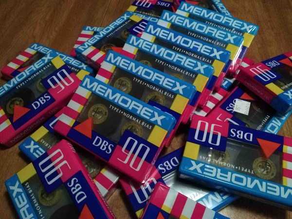
[Blaine Murphy] has set out to store an archive of visual art on cassette tape. To do so he encodes images via Slow-Scan Television (SSTV), an analogue technology from the late 50s which encodes images in for radio transmission. If you are thinking ‘space race’ you are spot on, the first images of the far side of the moon reached us via SSTV and were transmitted by the soviet Luna 3 spacecraft.
Yes, this happened
Encoding images with 5os technology is only one part of this ongoing project. Storage and playback are handled by a 90s tape deck and the display unit is a contemporary Android phone. Combining several generations in one build comes with its own set of challenges, such as getting a working audio connection between the phone and the tape deck or repairing old consumer electronics. His project logs on this topic are solid contenders for ‘Fail Of The Week’ posts. For instance, making his own belts for the cassette deck was fascinating but a dead end.
The technological breadth of the project makes it more interesting with every turn. Set some time aside this weekend for an entertaining read.
Just a couple of years back ham radio operators had the opportunity to decode SSTV beamed down from the ISS when they commemorated [Yuri Gagarin’s] birthday. Now if the mechanical part of this project is what caught your interest, you’ll also want to look back on this MIDI sampler which used multiple cassette players.
Hearing impairment, either partial or total, is a serious problem afflicting a large number of people. Almost 5% of the global population has some form of hearing disorder. For those affected by this disability from birth, it further impacts the development of language and speech abilities. In recent years, cochlear implants are increasingly being used to address this problem. These implants consist of two parts – the receiver and electrode array are implanted under the skin near the ear (with the electrode array terminating inside the Cochlea), while the microphone, electronics, transmitter and power source are attached on the outside. Often, the external unit has to be removed – for example, when the person needs to sleep. This is particularly so in the case of young children. The external unit is fairly large compared to their head and causes discomfort during sleep. And parents are worried that the expensive device could get damaged when the child is sleeping. This leads to the alarming situation where the child is asleep and has no audio sensory inputs being received from the surroundings. Not only can they not hear morning alarms, but also cannot react when there is an emergency situation such as a smoke alarm going off.
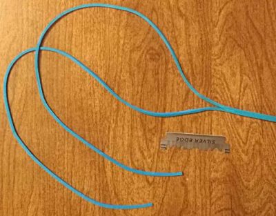
[Srdjan Pavlovic] came across this problem first hand when he visited his friend and learned about their six-year-old son with hearing loss since birth. The parents said their child will not be disturbed by loud noises at night since the external unit of his cochlear implant is removed each night. [Srdjan] then started work on building the Vibhear – an assistive hearing device to be used when the main hearing aid is removed or not working. It is a low-cost arm-band that provides a vibratory signal in response to high ambient noises.
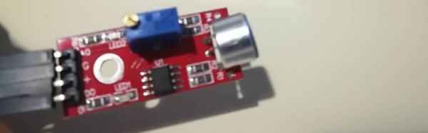
The main components are a microphone, amplifier, microcontroller and vibration motor powered by a LiPo battery through a boost converter/charger. An RTC module allows setting up daily wake up alarms. It’s currently prototyped around the Arduino, but the next iteration will use a specialized DSP which can be programmed to perform signal processing operations on input sound. This will allow identification of specific sounds such as car horns, barking dogs, smoke alarms or emergency sirens.
[Srdjan] is in the process of choosing components for his next iteration, so if you have any recommendations to help him choose the microcontroller, power supply controller or other parts, do let him know via comments below.
A few years ago, [Artem] learned about ways to focus sound in an issue of Popular Mechanics. If sound can be focused, he reasoned, it could be focused onto a plane of microphones. Get enough microphones, and you have a ‘sound camera’, with each microphone a single pixel.
Movies and TV shows about comic books are now the height of culture, so a device using an array of microphones to produce an image isn’t an interesting demonstration of FFT, signal processing, and high-speed electronic design. It’s a Daredevil camera, and it’s one of the greatest builds we’ve ever seen.
[Artem]’s build log isn’t a step-by-step process on how to make a sound camera. Instead, he went through the entire process of building this array of microphones, and like all amazing builds the first step never works. The first prototype was based on a flatbed scanner camera, simply a flatbed scanner in a lightproof box with a pinhole. The idea was, by scanning a microphone back and forth, using the pinhole as a ‘lens’, [Artem] could detect where a sound was coming from. He pulled out his scanner, a signal generator, and ran the experiment. It didn’t work. The box was not soundproof, the inner chamber should have been anechoic, and even if it worked, this camera would only be able to produce an image or two a minute.
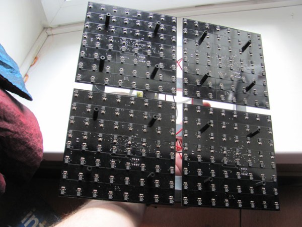
8×8 microphone array (mics on opposite side) connected to Altera FPGA at the center
The idea sat in the shelf of [Artem]’s mind for a while, and along the way he learned about FFT and how the gigantic Duga over the horizon radar actually worked. Math was the answer, and by using FFT to transform a microphones signals from up-and-down to buckets of frequency and intensity, he could build this camera.
That was the theory, anyway. Practicality has a way of getting in the way, and to build this gigantic sound camera he would need dozens of microphones, dozens of amplifiers, and a controller with enough analog pins, DACs, and processing power to make sense of all of this.
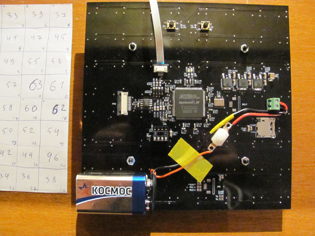
This complexity collapsed when [Artem] realized there was an off-the-shelf part that was a perfect microphone camera pixel. MEMS microphones, like the kind found in smartphones, take analog sound and turn it into a digital signal. Feed this into a fast enough microcontroller, and you can perform FFT on the signal and repeat the same process on the next pixel. This was the answer, and the only thing left to do was to build a board with an array of microphones.
[Artem]’s camera microphone is constructed out of several modules, each of them consisting of an 8×8 array of MEMS microphones, controlled via FPGA. These individual modules can be chained together, and the ‘big build’ is a 32×32 array. After a few problems with manufacturing, the board actually worked. He was recording 64 channels of audio from a single panel. Turning on the FFT visualization and pointing it at a speaker revealed that yes, he had indeed made a sound camera.
The result is a terribly crude movie with blobs of color, but that’s the reality of a camera that only has 32×32 resolution. Right now the sound camera works, the images are crude, and [Artem] has a few ideas of where to go next. A cheap PC is fast enough to record and process all the data, but now it’s an issue of bandwidth; 30 sounds per second is a total of 64 Mbps of data. That’s doable, but it would need another FPGA implementation.
Is this sonic vision? Yes, technically the board works. No, in that the project is stalled, and it’s expensive by any electronic hobbyist standards. Still, it’s one of the best to grace our front page.
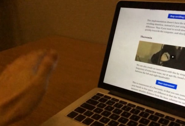
[Daniel]’s JavaScript library generates a sine wave at 20 kHz that’s played through the computer’s speakers. The frequency is high enough that it’s pretty much inaudible. While the tone is being played through the speakers, the computer’s microphone is used to sample the audio and calculate the frequency spectrum of the signal. As you move your hand closer to the computer while the tone is playing, the frequency of the received signal shifts higher; as you move your hand away, it shifts lower. [Daniel]’s script looks for this frequency shift and uses it to trigger events.
[Daniel] has some awesome examples included on his website where you can test out the functionality for yourself. He has a hands-free scrolling example, spectrum plot, and even a virtual theremin. Since his code is bundled up into an easy-to-use library, it should be fairly easy to integrate into any webpage. The only real limitation to the library is that it only works in Chrome right now (Firefox doesn’t support disabling echo cancellation).
Hearing aids are expensive little devices, typically costing a few thousand dollars each. They need to be highly integrated to fit in the ear, while still providing signal processing to ensure good audio quality.
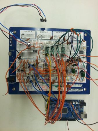
This DIY hearing aid does some intelligent signal processing. It uses an electret to capture audio, then uses a pre-amplifier to increase the gain 100 times. The next stage consists of four filters, dividing the input signal by frequency into four parts. These are passed into four LTC6910 programmable gain amplifiers, which allow an Arduino to control the gain of each channel. The LTC6910 takes 3 digital inputs that are used to set the gain value.
To determine which gain to use for each frequency band, the Arduino needs to know how much power is in each band. This could be done using a Fast Fourier Transform, but that would require quite a bit of processing power. Instead, an envelope detector averages the signal, which can be read by an analog input on the Arduino. Using this information, the hearing aid can boost specific frequencies when it detects conversation.
This hearing aid won’t quite fit in your ear, but there is a lot of interesting signal processing going on. The schematic, Arduino source code, and a MATLAB simulation are provided.


 [Artem]’s camera microphone is constructed out of several modules, each of them consisting of an 8×8 array of MEMS microphones, controlled via FPGA. These individual modules can be chained together, and the ‘big build’ is a 32×32 array. After a few problems with manufacturing, the board actually worked. He was recording 64 channels of audio from a single panel. Turning on the FFT visualization and pointing it at a speaker revealed that yes, he had indeed made a sound camera.