Raspberry Pi Driven Polargraph Exhibits High Precision Drawing Ability

This polar graph draws some amazing shapes on a dry erase board. Part of that is due to the mounting brackets used for the two stepper motors and the stylus. But credit is also due for the code which takes velocity into account in order to plan for the next set of movements.

The Go language is used to translate data into step commands for the two motors. This stream of commands is fed over a serial connection between the RPi board and an Arduino. The Arduino simply pushes the steps to the motor controllers. The inclusion of the RPi provides the horsepower needed to make such smooth designs. This is explained in the second half of [Brandon Green’s] post. The technique uses constant acceleration, speed, and deceleration for most cases which prevents any kind of oscillation in the hanging stylus. But there are also contingencies used when there is not enough room to accelerate or decelerate smoothly.

You can catch a very short clip of the hardware drawing a tight spiral in the video embedded after the break.

Continue reading “Raspberry Pi Driven Polargraph Exhibits High Precision Drawing Ability”

Thousands Of Physical Pixels Turn These Walls Into A Huge Display

The scale of this project is daunting. Each of the three white walls seen in the image above is made up of thousands of oblong square blocks. The blocks move independently and turn the room into an undulating 3D display.

If it had only been the demonstration video we might have run this as a “Real or Fake” post, but we’re certain this is real. Each pixel is made of what looks like a foam block mounted on a stepper-motor-driven linear actuator. So basically this must have set the world record for the CNC machine with the most axes. The motors make for very accurate and smooth motion, and the control software lets them draw shapes, words, animated objects, and the like. But the one side effects that we absolutely adore is the sound all of these motors make when running. After the break you can see a demo video and a ‘making of’ clip.

The installation is the work of the Jonpasang art collective and is installed as a Hyundai exhibit at an expo in Korea.

Continue reading “Thousands Of Physical Pixels Turn These Walls Into A Huge Display”

Logging Temperatures With An Etch-a-Sketch

What do you do if you’re given a gigantic ancient printer? If you’re [IronJungle], you throw that printer on your workbench and salvage all the parts you can. After coming across a few stepper motors in an old Oki printer, [IronJungle] decided to automate an Etch-a-Sketch with the help of a PIC microcontroller and H-bridge chip to log the ambient temperature on an Etch-a-Sketch display.

After [IronJungle] was finished figuring out his stepper motor circuit, the only thing left to do was to add a thermometer. For this task, he chose a very cool one-wire digital thermometer that carries power and data over the same wire.

In the video after the break, you can check out [IronJungle] playing with his new Etch-a-Sketch temperature logger with a shot glass of hot water and a cold can of holy water. There’s no scale or graph lines drawn on this Etch-a-Sketch temperature logger, but [IronJungle] has a few more things planned for this rig. We can’t wait to see those plans come to fruition.

Continue reading “Logging Temperatures With An Etch-a-Sketch”

A Closer Looks Helps You Build Your Own DiWire Bender

Whether or not you’re actually going to build this CNC wire bender, we think you’ll love getting a closer look at how it’s put together. The team over at PENSA got such a strong response from a look at the original machine that they decided to film a video (embedded after the break) showing how the thing was put together. They’ve also posted a repository with code, bom, etc.

In the image above [Marco] shows off the portion that actually does the bending. It’s designed to mount on the pipe through which the straightened wire is fed. The 3d printed mounting bracket really makes this a lot easier. The assembly provides a place to attach the solenoid which moves a bearing in and out of position. That bearing presses against the wire to do the bending, but must be moved from one side of the wire to the other depending on the direction of the next bend. This is a lot easier to understand after watching the demo video which is also embedded after the break.

Continue reading “A Closer Looks Helps You Build Your Own DiWire Bender”

Your Mug On An Etch A Sketch — Automatically

[Jim’s] pretty serious about his Etch a Sketch. He’s gone to the trouble of building a rig that will automatically render a photograph as Etch a Sketch art. Do you recognize the US political figure being plotted in this image? He actually cracks these open and removes all of the internals to preserve the artwork when the reassembled body is ready to be hung on a wall. But we like it for the hacker-friendly interface techniques he used.

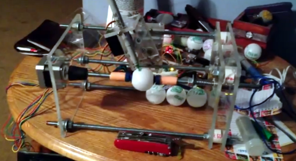
He moves the knobs using a pair of stepper motors. They attach thanks to a pair of 3D printed gears he modeled which go over the stock knobs and secure with four set screws. He says he can be up and printing in five minutes using these along with the MDF jig that holds the body and the motors.

He converts photos to 1-bit images, then runs them through ImageMagick to convert them into a text file. A Python script parses that text, sending appropriate commands to an Arduino which drives the motors. The image is drawn much like a scanning CRT monitor. The stylus tracks one horizontal line at a time, drawing a squiggle if the pixel should be black, or skipping it if it should be white.

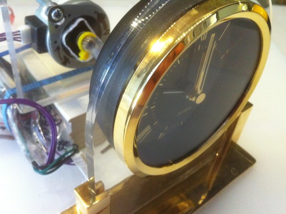
We wish there was a video of the printing process. Since we didn’t find one, there’s a bonus project unrelated to this one after the break. It’s an Etch a Sketch clock.

Continue reading “Your Mug On An Etch A Sketch — Automatically”

Robotic Whiteboard Writes Your Wall On The Wall

[Dave’s] drawbot writes his Facebook wall messages on a whiteboard. The setup is pretty simple, depending on a pair of stepper motors and common household goods. As you can see in the image, the stylus is a plain old dry-erase marker held by a big spring clip (the kind that holds a stack of papers together). What you can’t see is that there’s a kick stand to hold the writing head away from the board when moving to the next plot point.

In this example a cursive font is being used, but [Dave] included two other fonts in the code. Those require the felt tip to be frequently lifted from the board, and a servo motor does this by pressing a cotton swab against the surface. This does erase any marker lines it slides past, but it’s a pretty small area that is lost. To control the motors [Dave] is using the EiBotBoard which was originally designed for the EggBot. It’s got a USB mini-b connector which lets a computer push messages scraped from the Internet. Don’t miss the video demonstration embedded after the break.

A small modification would make this into a pretty nifty light painting rig.

Continue reading “Robotic Whiteboard Writes Your Wall On The Wall”

Automated Turntable Photography

[Muris] has a friend who is selling items on the internet. This friend wanted a simple way to make rotating images of the products and asked him to help. The result of his labors is this base unit that drives the turn table and controls the camera.

The first iteration of the turntable was powered by the stepper motor from a floppy drive. A disc was mounted directly on the motor spindle, but the results were a bit poor. This is because the motor had a fairly low resolution of 200 steps per rotation. That doesn’t allow for smooth animation, and there was a lot of vibration in the system. An upgrade to the geared system you see above included swapping out that motor for one from an old scanner. Now it achieves 1200 steps per rotation and the vibration is gone.

The connectors seen in the base are USB, incoming power, and shutter control. [Muris] wrote a program to control the PIC 16F628A inside the base. The program sends commands via USB and has parameters for number of frames per rotation, direction of rotation, and the like. Set it up as desired, place the product on the turntable, and hit start. Unfortunately there’s no video of this in action because [Muris] gave it to his friend as soon as it was finished. We guess the fact that he didn’t get it back means it’s working great.

If you don’t mind some rough edges and exposed wiring you can throw a system of your own together pretty quickly.