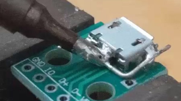
Soldering iron tip heating up a piece of wire wrapped around the metal parts of a MicroUSB socket, with melted solder heating up all the important parts.

Desoldering Without Hot Air: Piece Of Wire Edition

Quite a few hackers nowadays share their tips and tricks on Twitter – it’s easy to do so, and provided either an existing audience or a bit of effort to get one, you’ll get at least a few notifications telling you that people appreciated what you had to share. Today, we’re covering two desoldering hacks highlighted there that will be useful some day, exactly when you need them. Both of them use a piece of wire and, in a way, extend the reach of your soldering iron’s tip. Copper wire would work better because of superior thermal conductivity, but other types of solid core wire will work in a pinch.

First hack is brought to us by [Erin Rose] – desoldering a microUSB socket. You need to heat up the entire shield and the pins at the same time, which the wire acts as a thermal gateway for. As long as there are melted solder bridges from sections of the wire to all the copper-to-part connection points, it should be easy to pump enough heat into the solder joints for all of them to eventually melt and give in at once.

Second hack is brought to us by [arturo182]. A piece of thick wire acts, again, as a heat conductor to desolder a 0.5mm pitch TQFP-100 package IC. You have to bend the wire into a correct shape, so that it’s as close to the pins of the TQFP as possible. In this situation, the wire performs two functions: first, transferring the heat from the iron’s tip to different points along the wire, then, as a barrier that helps solder not escape too far away from the pins. Copious amounts of flux likely desired for this one!

Hopefully, this comes handy if you ever need to replace an all-SMD part ASAP but don’t have a hot air gun or a hotplate handy. After getting this concept down to an art, we are sure you won’t limit yourself to TQFP parts and MicroUSB sockets. We’ve talked about desoldering practices before as part of our newsletter, and using lots of melted solder for part removal is not a foreign concept to us, either.

Continue reading “Desoldering Without Hot Air: Piece Of Wire Edition”

Hacklet 99 – Soldering Tools

If there is one tool every hardware hacker needs, it’s a good soldering setup. Soldering irons, heat guns, reflow ovens and the like make up the tools of the trade for building electronic circuits. Spend enough time working with a tool, and you’ll find a way to improve it. It’s no surprise that hackers, makers, and engineers have been hacking their soldering tools for decades. This week’s Hacklet features some of the best soldering tool projects on Hackaday.io!

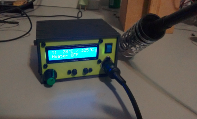
hakkoWe start with  [Kuro] a Hakko 907 based Soldering Station. Hakko 907 and 936 soldering station clones from the Far East are available all over the internet. While the heaters work, none of them have very good temperature controllers. [Kuro] turned a problem into a project by building his own soldering station. These irons are rated for 24 V. 24 volt power supplies are not very common, but it’s easy to find old 19 volt supplies from discarded laptops. [Kuro] found that the lower voltage works just fine. An Arduino nano controls the show, with user output displayed on a 2 line LCD. The finished controller works better than the original, and probably would give a real Hakko model a run for its money.

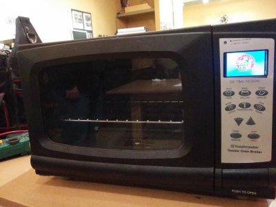
reflowNext up is [Sukasa] with Reflow Oven. When MakerSpace Nanaimo needed a reflow oven, [Sukasa] jumped in with this design. The idea was to create an oven that looked unmodified – just think of it as the toaster oven of the future, or the reflow oven of today. A Netduino plus 2 is the main controller. User information is displayed on a color TFT LCD. This oven is even internet connected, with an internally hosted web page and JSON data feed. The Netduino controls two beefy Solid State Relays (SSRs). The SSRs handle the dirty work of switching the oven’s heating elements. Two fans keep air moving to avoid hot spots. Precision temperature sensing is achieved through a pair of Adafruit MAX31855 breakout boards reading thermocouples.

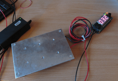
plateNext we have [Jaromir Sukuba] with Soldering preheat plate. When soldering surface mount components, like QFN or BGA parts, it helps to pre-heat the whole board. There are commercial products to do this using hot air and other techniques, but it really comes down to making a hotplate. [Jaromir] figured he could do a pretty good job at this, so he built his own with a 3mm aluminum plate. Heat comes from 6 resistors in TO-220 cases. A Microchip PIC18 monitors a thermocouple and keeps things from getting too hot. For power, [Jaromir] had the same idea as [Kuro] did, and used a 19V power brick from an old laptop.

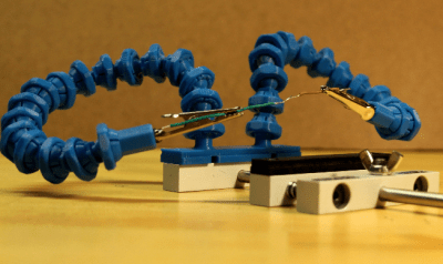
gooseFinally we have [Alex Rich] with Locking ball and socket gooseneck system. [Alex] came up with the Stickvise, so it’s fitting that he comes up with an awesome upgrade for it. We’ve all fought with “helping hands” while soldering. You never get them at quite the right angle. This system fixes that with a simple ball and gooseneck setup. [Alex] saw a similar design and printed it out. While it worked, the pieces popped apart too easily. [Alex] redesigned the system, adding a threaded locking ring. These new goosenecks stay put, holding your work exactly where you want it.

If you want to see more soldering tool projects, check out our brand new soldering tools list! If I missed your project, don’t be shy! Just drop me a message on Hackaday.io. That’s it for this week’s Hacklet. As always, see you next week. Same hack time, same hack channel, bringing you the best of Hackaday.io!

PIC 18F4550 Dev Board

[Natsfr] was looking for a single-sided PCB to host a PIC 18F4550. Not finding one he designed his own in Kicad and is sharing (translated) the spoils of his labor.

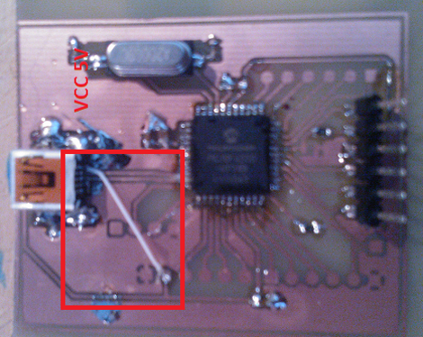
This chip has USB capabilities which is why we see it used in a ton of projects. Almost all of them (including this USB input device post) use a very large DIP package. [Natsfr] went a different route, designing for the TQFP package to keep the drilling ot a minimum. The layout includes a crystal and USB-mini port, but it also breaks out the I/O pins on the chip. The red box above shows the quick fix he used on the VCC line as the board trace was shorting on the USB jack housing.

He didn’t drill out the holes for most of the breakout pins on this prototype. There’s just one header populated for programming the PIC chip. But he does have some plans for the first board. He’s going to use [Texan’s] AVR programming firmware for PIC to turn it into a USB AVR ISP programmer.