Cavity Filters, The Black Art You Have A Chance Of Pursuing

A tuned circuit formed by a capacitor and an inductor is a familiar enough circuit, and it’s understood that it will resonate at a particular frequency. As that frequency increases, so the size of the capacitor and inductor decrease, and there comes a point at which they can become the characteristic capacitance and inductance of a transmission line. These tuned circuits can be placed in an enclosure, at which they can be designed for an extremely high Q factor, a measure of quality, and thus a very narrow resonant point. They are frequently used as filters for that reason, and [Fesz] is here with a video explaining some of their operation and configurations.

Some of the mathematics behind RF design can be enough to faze any engineer, but he manages to steer a path away from that rabbit hole and explain cavity filters in a way that’s very accessible. We learn how to look at tuned circuits as transmission lines, and the properties of the various different coupling methods. Above all it reveals that making tuned cavities is within reach.

They’re a little rare these days, but there was a time when almost every TV set contained a set of these cavities which were ready-made for experimentation.

Continue reading “Cavity Filters, The Black Art You Have A Chance Of Pursuing”

Siphoning Energy From Power Lines

The discovery and implementation of alternating current revolutionized the entire world little more than a century ago. Without it, we’d all have inefficient, small neighborhood power plants sending direct current in short, local circuits. Alternating current switches the direction of current many times a second, causing all kinds of magnetic field interactions that result in being able to send electricity extremely long distances without the resistive losses of a DC circuit. The major downside, though, is that AC circuits tend to have charging losses due to this back-and-forth motion, but this lost energy can actually be harvested with something like this custom-built transformer.

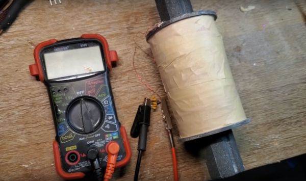
[Hyperspace Pilot] hand-wound this ferromagnetic-core transformer using almost two kilometers of 28-gauge magnet wire. The more loops of wire, the more the transformer will be able to couple with magnetic fields generated by the current flowing in other circuits. The other thing that it needs to do is resonate at a specific frequency, which is accomplished by using a small capacitor to tune the circuit to the mains frequency. With the tuning done, holding the circuit near his breaker panel with the dryer and air conditioning running generates around five volts. There’s not much that can be done with this other than hook up a small LED, since the current generated is also fairly low, but it’s an impressive proof of concept.

After some more testing, [Hyperspace Pilot] found that the total power draw of his transformer is only on the order of about 50 microwatts in an ideal setting where the neutral or ground wire wasn’t nearby, so it’s not the most economical way to steal electricity. On the other hand, it could still be useful for detecting current flow in a circuit without having to directly interact with it. And, it turns out that there are better ways of saving on your electricity bill provided you have a smart meter and the right kind of energy-saving appliances anyway.

Continue reading “Siphoning Energy From Power Lines”

Permeability Tuned Oscillators Made Stable With A Glue Stick

For over a century now, radio amateurs have made tuned circuits using a coil of wire and a variable capacitor. In recent decades the supply of variable capacitors has dwindled, as SDR technology has supplanted the traditional tuning capacitor. No more tuned circuits for the radio amateurs? Not quite, as [Bill Meara N2CQR] shows us in the video below the break by making variable inductors using permeability tuning. This is hardly high-tech, the major component is as simple as a glue stick.

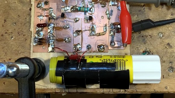
A permeability tuned inductor has a core that is moved in and out of its center by means of a screw. A glue stick has a glue core on a lead screw from a knob at its end, so an old glue stick with the glue replaced by a ferrite ring makes a reasonable permeability tuned former. The coil is wound on its outside, and when assembled into an oscillator it gives a useful tuning range. This is hardly a new idea as permeability tuning could be found in car radios and TV tuners among other applications back in the day, but it’s still a good trick to bear in mind.

We’ve featured plenty of Bill’s videos before here at Hackaday, most recently tracking down an unusual early TV.

Continue reading “Permeability Tuned Oscillators Made Stable With A Glue Stick”

NFC Performance: It’s All In The Antenna

NFC tags are a frequent target for experimentation, whether simply by using an app on a mobile phone to interrogate or write to tags, by incorporating them in projects by means of an off-the-shelf module, or by designing a project using them from scratch. Yet they’re not always easy to get right, and can often give disappointing results. This article will attempt to demystify what is probably the most likely avenue for an NFC project to have poor performance, the pickup coil antenna in the reader itself.

A selection of the NFC tags on my desk

The tags contain chips that are energised through the RF field that provides enough power for them to start up, at which point they can communicate with a host computer for whatever their purpose is.

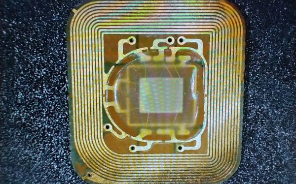
“NFC” stands for “Near Field Communication”, in which data can be exchanged between physically proximate devices without their being physically connected.  Both reader and tag achieve this through an antenna, which takes the form of a flat coil and a capacitor that together make a resonant tuned circuit. The reader sends out pulses of RF which is maintained once an answer is received from a card, and thus communication can be established until the card is out of the reader’s range. Continue reading “NFC Performance: It’s All In The Antenna”

Low-End Parts Make Tesla Coil With A High-End Look

We all know the saying: cheap, fast, or good — pick any two. That rule seems to apply across the spectrum of hackerdom, from software projects to hardware builds. But this DIY Tesla coil build might just manage to deliver on all three.

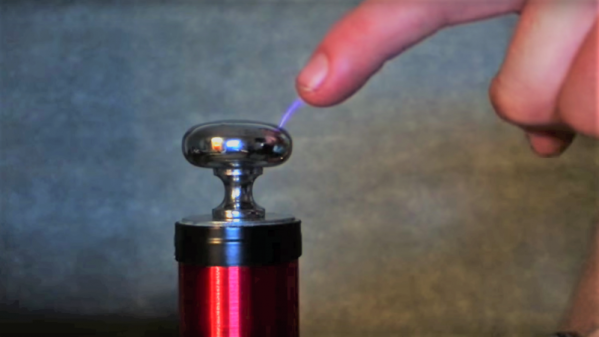
Cheap? [Jay Bowles]’ Tesla coil is based on a handheld bug zapper that you can find for a couple of bucks, or borrow from the top of the fridge in the relatively bug-free winter months. The spark gap is just a couple of screws set into scraps of nylon cutting board — nothing fancy there. Fast? Almost everything needed to build this is stuff lying around the house, and depending on the state of your junk bin you may not even have to order the polypropylene caps [Jay] recommends. Good? That’s a relative term, of course, and if you define it as a coil capable of putting out pumpkin-slaying lightning bolts or playing “Yakkity Sax”, you’ll likely be disappointed. But there’s no denying that this Tesla coil looks good, from its Lexan base to the door-pull top load. And running off a couple of AA batteries, it’s safe to use too.

[Jay] put a lot of care into winding and dressing the secondary coil neatly, and the whole thing would look great as a desktop toy. Not into the winding part? You can always etch a PCB Tesla coil instead.

Continue reading “Low-End Parts Make Tesla Coil With A High-End Look”

Radio Tuning The Quicksilver Way

Modern radios are often digital affairs, in which the frequency is derived from a stable crystal oscillator and varied through a microprocessor controlled frequency synthesiser. It won’t drift, and it’s exactly on the frequency dialed in. Older radios though relied on a tuned circuit, a combination of capacitor and inductor, for their frequency selection. If you were curious enough to peer inside — and we know you were — you’d have seen the moving vanes of a variable capacitor controlled by the tuning knob.

Of course, there is another way to adjust a tuned circuit: by changing the value of the inductor. Older car radios for instance moved a ferrite slug inside a coil to tune from station to station. But that method is not good enough for [David Mills]. Being in possession of some finely graduated syringes he decided to try liquid tuning by increasing the volume within the coil.

Solutions of salts made little difference, so he reached for some mercury. The result is an RF inductor wound round a syringe body, with a body of mercury whose position can be adjusted by the plunger. He measures the Q factor of the coil with air core or mercury core, and as the inductance decreases with more mercury, so does the Q.

We see home-made parts from time to time, and there’s nothing too special about permeability tuning. However, this unusual take on the matter makes this one rather special. We doubt we’ll see its like very often in the future.