If you are of a certain age you may have worked in an office in the days before the computer revolution, and the chances are that in the corner of your office there would have been a teletype machine. Like a very chunky typewriter with a phone attached, this was an electromechanical serial terminal and modem, and machines like it would have formed the backbone of international commerce in the days before fax, and then email.
Teletypes may have disappeared from the world of trade, but there are a surprising number still in private hands. Enthusiasts collect and restore them, and radio amateurs still use digital modes based on their output. The problem facing today’s teletype owner though is that they are becoming increasingly difficult to interface to a modern computer. The serial port, itself an interface with its early history in the electromechanical world, is now an increasingly rare sight.
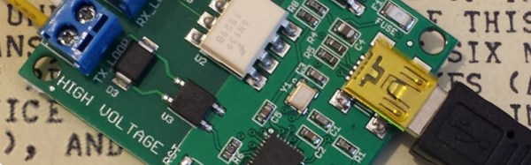
[Eric] has a project which addresses the teletype owner’s interfacing woes, he’s created a board with all the necessary level shifters and an Atmega32u2 microcontroller to translate the teletype’s output to USB.
In his design he’s had to solve a few problems related to such an aged interface. Teletypes have a serial output, but it’s not the TTL or RS232 we may be used to. Instead it’s a high-voltage current loop designed to operate electromagnets, so his board has to incorporate an optocoupler to safely isolate the delicate computer circuitry. And once he had the teletype’s output at a safe level he then had to translate its content, teletypes speak 5-bit ITA2 code rather than our slightly newer 7-bit ASCII.
The result though is a successful interface between teletype and computer. The former sees another teletype, while the latter sees a serial terminal. If you have a teletype and wish to try it for yourself, he’s released the source code in a GitHub repository.
Teletypes have featured a few times here at Hackaday over the years. We’ve had one as an SMS client, another that monitors a Twitter feed, and while it’s not strictly a teletype, a close examination of an Olivetti mechanical serial terminal.