3D Printing In Custom PLA With A TPU Core

[Stefan] from CNC Kitchen explored an unusual approach to a multi-material print by making custom PLA filament with a TPU core to make it super-tough. TPU is a flexible filament whereas PLA is hard almost to the point of being brittle. The combo results in a filament with some unusual properties, inviting some thoughts about what else is possible.

Cross-section of 3D print using white PLA with a red TPU core.

[Stefan]’s video covers a few different filament experiments, but if you’d like to see the TPU-PLA composite you can skip ahead to 18:15. He first creates the composite filament by printing an oversized version on a 3D printer, then re-forming it by running it through a Recreator to resize it down to 1.75 mm.

We have seen this technique of printing custom filaments before, which is useful to create DIY multi-color filaments in small quantities right on a 3D printer’s print bed with no special equipment required. This is an effective method but results in filament with a hexagonal profile, which works but isn’t really ideal. By printing his custom composite at 4 mm diameter then resizing the filament down to 1.75 mm, [Stefan] was able to improve overall printability.

That being said, TPU and PLA have very different characteristics and don’t like to adhere to one another so the process was pretty fiddly. TPU-cored PLA might be troublesome and uncooperative to make, but it can be done with some patience and fairly simple equipment.

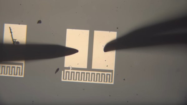
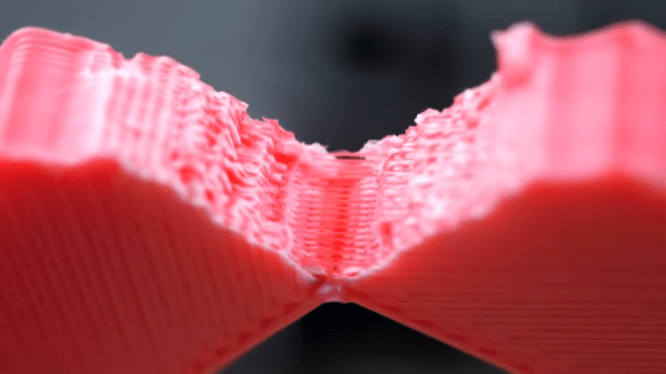
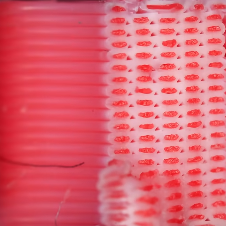
Despite the difficulties, test prints were pretty interesting. PLA toughness was roughly doubled and under magnification one can see a lattice of TPU strands throughout the prints which are unlike anything else. Check it out in the video, embedded below.

Continue reading “3D Printing In Custom PLA With A TPU Core”

Almost Making A Camera Sensor From Scratch

On our travels round the hardware world we’ve encountered more than one group pursuing the goal of making their own silicon integrated circuits, and indeed we’ve seen [Sam Zeloof] producing some of the first practical home-made devices. But silicon is simply one of many different semiconductor materials, and it’s possible to make working semiconductor devices in a less complex lab using some of the others. As an example, [Breaking Taps] has been working with copper (II) oxide, producing photodiodes, and coming within touching distance of a working matrix array.

The video below the break is a comprehensive primer on simple semiconductor production and the challenges of producing copper (II) oxide rather than the lower temperature copper (I) oxide. The devices made have a Schottky junction between the semiconductor and an aluminium conductor, and after some concerns about whether the silicon substrate is part of the circuit and even some spectacular destruction of devices, he has a working photodiode with a satisfying change on the curve tracer when light is applied. The finale is an array of the devices to form a rudimentary camera sensor, but sadly due to alignment issues it’s not quite there  yet. We look forward to seeing it when he solves those problems.

As we’ve seen before, copper oxide isn’t the only semiconductor material outside the silicon envelope.

Continue reading “Almost Making A Camera Sensor From Scratch”

Tool-Building Mammals

It’s often said of us humans that we’re the only “tool-using mammals”. While not exclusive to the hacker community, a bunch of us are also “tool-building mammals” when we have the need or get the free time. I initially wanted to try to draw some distinction between the two modes, but honestly I think all good hackers do both, all the time.

We were talking about the cool variety of test probes on the podcast, inspired by Al Williams’ piece on back probes. Sometimes you need something that’s needle-thin and can sneak into a crimp socket, and other times you need something that can hold on like alligator clips. The infinite variety of jigs and holders that make it easier to probe tiny pins is nothing short of amazing. Some of these are made, and others bought. You do what you can, and you do what you need to.

You can learn a lot from looking at the professional gear, but you can learn just as much from looking at other hackers’ bodge jobs. In the podcast, I mentioned one of my favorite super-low-tech hacks: making a probe holder out of a pair of pliers and a rubber band to hold them closed. Lean this contraption onto the test point in question and gravity does the rest. I can’t even remember where I learned this trick from, but I honestly use it more than the nice indicator-arm contraptions that I built for the same purpose. It’s the immediacy and lack of fuss, I think.

So what’s your favorite way of putting the probe on the point? Home-made and improvised, or purpose-built and professional? Or both? Let us know!

How Does The Raspberry Pi Rack Up Against A Mini PC?

When the first Raspberry Pi came out back in 2012 it was groundbreaking because it offered a usable little Linux machine with the proud boast of a $25 dollar price tag. Sure it wasn’t the fastest kid on the block, but there was almost nothing at that price which could do what it did. Three leap years later though it’s surrounded by a host of competitors with similar hardware, and its top-end model now costs several times that original list price.

Meanwhile the cost of a “real” x86 computer such as those based upon the Intel N100 has dropped to the point at which it almost matches a fully tricked-out Pi with storage and peripherals, so does the Pi still hold its own? [CNX Software] has taken a look.

From the examples they use, in both cases the Intel machine is a little more expensive than the Pi, but comes with the advantage of all the peripherals, cooling, and storage coming built-in rather than add-ons. They rate the Pi as having the advantage on expandability as we’d expect, but the Intel giving a better bang for the buck in performance terms. From where we’re sitting the advantage of the Pi over most of its ARM competition has always been its good OS support, something which is probably exceeded by that on an x86 platform.

So, would you buy the Intel over the high-end Pi? Let us know in the comments.

the PTC fuse to blame for the fault described, on the ROG Ally board, with a wire soldered across the fuse

ROG Ally SD Card Slot Fix Shines Light On PTC Fuse Failure Modes

The Asus ROG Ally is a handheld that, to our pleasant surprise, has attracted a decently sized modding community. Recently, we’ve stumbled upon a Reddit post investigating a somewhat common failure mode of this handheld — the microSD card slot going out of order, where an inserted card fails to be recognized, pretty irritating to encounter. Now, it turns out, this is down to a certain model of PTC fuses being failure-prone.

It makes sense to fuse the SD card slot. The cards are dense pieces of technology that are subject to some wear and tear in daily use. As such, it’s not unheard of that a microSD card can short-circuit internally — heating up to the point of melting plastic and giving people severe burns. Given that such a card is typically connected to a beefy 3.3 V rail, any mass-manufactured device designer could want to put a fuse between the 3.3 V rail and the card. However, on some ROG Ally batches, a certain make of the fuse is used, that appears to be likely to develop faults: the fuse’s resistance increasing dramatically during the card’s normal operation, with the SD card being supplied subpar power as a result.

There’s a fair bit of investigating happening in the comment section, with people posting oscilloscope captures, using breakouts to tap the SD card, and figuring out the fuse part numbers for the affected models. As for Reddit’s solution, it’s short-circuiting the fuse with a piece of thin wire — we would probably source a suitable fuse and solder it on top of the faulty one.

This isn’t the first ROG Ally modification we’ve covered so far, and given the activity we’re seeing, it’s unlikely to be our last.

Here’s How That Disney 360° Treadmill Works

One thing going slightly viral lately is footage of Disney’s “HoloTile” infinite floor, an experimental sort of 360° treadmill developed by [Lanny Smoot]. But how exactly does it work? Details about that are less common, but [Marques Brownlee] got first-hand experience with HoloTile and has a video all about the details.

HoloTile is a walking surface that looks like it’s made up of blueish bumps or knobs of some kind. When one walks upon the surface, it constantly works to move its occupant back to the center.

Whenever one moves, the surface works to move the user back to the center.

Each of these bumps is in fact a disk that has the ability spin one way or another, and pivot in different directions. Each disk therefore becomes a sort of tilted wheel whose edge is in contact with whatever is on its surface. By exerting fine control over each of these actuators, the control system is able to create a conveyor-belt like effect in any arbitrary direction. This can be leveraged in several different ways, including acting as a sort of infinite virtual floor.

[Marques] found the system highly responsive and capable of faster movement that many would find comfortable. When walking on it, there is a feeling of one’s body moving in an unexpected direction, but that was something he found himself getting used to. He also found that it wasn’t exactly quiet, but we suppose one can’t have everything.

How this device works has a rugged sort of elegant brute force vibe to it that we find appealing. It is also quite different in principle from other motorized approaches to simulate the feeling of walking while keeping the user in one place.

The whole video is embedded just below the page break, but if you’d like to jump directly to [Marques] explaining and showing exactly how the device works, you can skip to the 2:22 mark.

Continue reading “Here’s How That Disney 360° Treadmill Works”

Google Removes RISC-V Support From Android

Last year the introduction of  RISC-V support to the Android-specific, Linux-derived Android Common Kernel (ACK) made it seem that before long Android devices might be using SoCs based around the RISC-V ISA, but it would seem that these hopes are now dashed. As reported by Android Authority, with a series of recently accepted patches this RISC-V support was stripped again from the ACK. While this doesn’t mean that Android cannot be made to work on RISC-V, any company interested would have to do all of the heavy lifting themselves, which might include Qualcomm with their recently announced RISC-V-based smartwatch Snapdragon SoC.

No reason was provided by Google for this change, and the official statement from Google to Android Authority says that Google is not ready to provide a single supported Android Generic Kernel Image (GKI), but that ‘Android will continue to support RISC-V’. This change however, removes RISC-V kernel support from the ACK, and since Google only certifies Android builds which ship with a GKI featuring an ACK, this effectively means that RISC-V is not supported at this point, and likely won’t be for the foreseeable future.

As discussed on Hacker News, a potential reason might be the very fragmentary nature of the RISC-V ISA, which makes a standard RISC-V kernel very complicated if you want to support more than a (barebones) profile. This is also supported by a RISC-V mailing list thread, where ‘expensive maintenance’ is mentioned for why Google doesn’t want to support RISC-V.