Mug Plotter Based On The Egg-Bot

mug-plotter

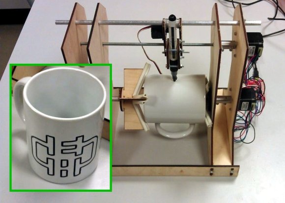
Here’s a fun way to break up the monotony in the old cubicle farm. The Mug Plotter will let you expertly inscribe your coffee vessel with a different witty saying or design for each day of the week. If it looks familiar that’s because it’s loosely based on the non-flat drawing robot, the Egg-Bot.

[Teed] built the machine using laser cut plywood parts. He starts off the build description with the griping technique. There are two parts to this, one is concave and fits in the mouth of the mug. The convex side grips the bottom edges of it. These parts go on the frame along with the slide and thread rods which hold the stylus. A servo motor is along for the ride, providing the ability to lift the marker when necessary.

You can see in the clip after the break that there’s a bit of oscillation in the rig when one of the steppers starts turning really fast. But it doesn’t seem to affect the look of the design very much at all.

Continue reading “Mug Plotter Based On The Egg-Bot”

ASETNIOP Chorded Typing With A Piano Keyboard

asetniop-chorded-typing-with-a-piano

We don’t know if typing your Facebook updates from a piano keyboard counts as practicing or not. But if you want to give it a try here’s how. [Zach] wrote in to our tips line with his latest ASETNIOP hack which uses a MIDI piano keyboard to touch type on a computer.

Last July was when we first heard about ASETNIOP. It’s a chorded typing system which at the time was aimed at, but not limited to, touch screen devices. This version gives a pretty good idea of how the system actually works. Your fingers and thumbs are each assigned a key and they never move away from it. To type more than just the ten letters, combinations of keys are assigned the rest of the alphabet. You can see the piano example of the system after the break. But better yet would be hooking your own MIDI keyboard up to the computer and trying it in a browser.

Continue reading “ASETNIOP Chorded Typing With A Piano Keyboard”

Script Makes Custom Pinout Labels For Your Chips

cusom-pinout-labels

After years of prototyping hobby electronics we’ve learned (several times actually) that when something’s not working it’s a problem with the hardware. Usually the jumper wires aren’t hooked up correctly, or we needed to throw a pull-up resistor in and forgot to. One thing that can really help sort these problems out quickly is a pinout label for each chip like the ones seen above. This is a project which [John Meacham] came up with. It uses a script to generate chip pinouts on a label maker.

The label maker he started with is a Brother PT-1230PC. It connects to a computer via USB and can use a few different widths of self adhesive label tape. [John] found that the 1/4″ wide tape is nearly a perfect fit for PDIP components.

His script takes a YAML file as the input. This formatting standard makes is quick an easy to whip up a label for a new chip using just your text editor. From there his Pearl script turns the data into a Portable Network Graphics (.png) file with the labels spaced for the 0.1″ pitch of the chip. Send this graphic to your label maker and you’ve got an adhesive reminder that will help reduce the time you spend pawing through datasheets just for the pinouts.

Adding Fireplace Control To Your Home Automation

fireplace-automation

[James] has an admirable home automation system which he’s been working on for years. It does things like monitor the state of the garage door, control the lights, and it even notifies him of a power failure. One thing that wasn’t on the system yet are the fireplaces he has in his home. The hardware you see above is how he patched into the fireplace remote control system in order to automate them.

The remote control uses RF to communicate with a base station. Unlike controlling home theater components which use IR, this makes it a bit more difficult to patch into. Sure, we’d love to see some reverse engineering of the protocol so that a simple radio module could be used, but [James] chose the route which would mean the least amount of hacking on his part. He soldered wires onto the PCB for the buttons and connected to them using reed relays. These let the Arduino simulate button presses.

With the rig connected to the home network he has a lot of options. The system can sense if the house is occupied. If it determines that no one is home it will switch off the fireplaces. [James] also mentions the ability to monitor for carbon monoxide or house fires, switching off the gas fireplaces in either case.

Repairing Broken Injection Molded Parts With A 3D Printer

injection-molded-part-repair

The value of a 3D printer is obvious for people who hack hardware as a hobby. But this repair project should drive home their usefulness for the commoner. [James Bruton] used a 3D printer to recreate a hopelessly broken injection molded plastic part. This is a suction cup mounting bracket for a Tom Tom GPS module. The sphere which makes it adjustable had broken off of the column holding it. For 100% of non-hacking consumers that’s the end of this item. We can’t see a fix that would restore the strength of the original part.

The replacement starts by measuring the broken part with precision calipers. [James] then grabbed a copy of 123D, which is free software. He starts by modeling the sphere, then builds up the support column and the base with a cut-out. It’s obvious he’s already very familiar with the software, but even the uninitiated should be able to get this done pretty quickly. After slicing the design for the 3D printer he finds the part will be ready in about 11 minutes. The first prototype is a bit too small (the ball requires close tolerances to work well). He spins up a second version which is a bit large and uneven. A few minutes of filing leaves him with a smooth sphere which replaces the original part beautifully!

You can see the entire design, print, and assembly process in the clip after the break.

Continue reading “Repairing Broken Injection Molded Parts With A 3D Printer”

Enabling An Unused Touchscreen Overlay On A Consumer LCD

uncovering-an-unused-touchscreen-on-a-consumer-lcd

When [Andrei] first got his Raspberry Pi he wanted to make it a standalone computer right away. This means the normal input devices like a mouse and keyboard, but also some type of display. To avoid waiting for shipping he ended up using a cheap vehicle backup camera screen from the local big box store. It worked great, and recently he decided he would try to convert it to run off of 5V power to simplify his setup. While snooping around inside the device he discovered an unused resistive touch overlay and figured out how to get it to work.

What tipped him off is the small four-conductor connector which wasn’t hooked up to anything. He carefully soldered wires onto the flexible circuit traces, then generously covered them in hot glue to help prevent movement from breaking the rigid connection. To get this working you need to measure the resistance between the conductors. Most of the time we figure the RPi GPIO header can be used directly, but for this task an intermediary is necessary. [Andrei] went with a small Arduino clone board. A bit of trial and error was all it took to get the connections right and to iron out the code which translates the values into coordinates.

Deploying An Open Source Pollution Monitoring Network

pollution-monitoring-network

[Kasey] and [Guyzmo] have been working for the past couple of years on a side project that lets them monitor pollution using a network of sensors. They’ve just decided to make the project open source, both hardware and software. The details of the system are available at their GitHub repository.

There are two main components to the system. On the right is a base station which collects the data from the array of sensor, one of which is shown on the left. Each sensor runs off of a battery, but features a PV solar panel which keeps the power source topped off. It uses an Arduino to drive the system, and an XBee radio for communications. Some info about the sensors can be found on this summary page. There’s a PM10 particle pollution sensor, temperature, sound, nitrogen, and oxygen sensors. We also wonder if any data can be gleaned from how much electricity the solar panel is able to harvest?

The base station also uses an XBee radio to poll the network, but it’s not driven by an Arduino. They’ve gone with the ARM-based BeagleBone to manage the data.