With inexpensive microntrollers capable of the most impressive feats of sound synthesis, it’s not so often we see projects that return to an earlier style of electronic music project. The 1-bit synth from [Electroagenda] takes us firmly into that territory, employing that most trusty of circuits, a 555.
It’s a time-honored circuit, a 555 provides a note clock that drives a 4017 that functions as a sequencer. This switches in a set of voltage dividers, which in turn control another 555 oscillator that produces the notes. It’s a fun toy straight from the 1970s, right down to the protoboard and hookup wire construction. There’s a demo video with some lovely beeps below, and we think most of you should have what it takes to make your own.
If you’re seeking more inspiration, may we introduce you to our Logic Noise series?
‘Tis the season for holiday hacks, and [Ben Emmett] is here to remind us that we don’t necessarily need a fancy microcontroller in order to make flashy fun things happen.
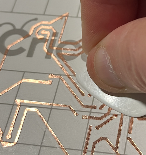
Smoothing down the copper traces with a guitar pick.
Take this Christmas tree for example, which uses a 555 timer and a CB4017 decade counter in order to drive some blinking LEDs. The ICs are through-hole, making the circuit fairly accessible to new players, but there are a few SMD components that need soldering as well. (More on that later.)
Here, the 555 acts like a clock and drives a square wave. Using the clock as input, the decade counter toggles the output pins one after the other, driving the LEDs to blink in turn. Since there are only eight lights, there is a pause in the light-up pattern, but that could be fixed by wiring decade counter output #9 to the reset pin.
Although function was the main focus circuit-wise, [Ben] managed to lay the traces in the shape of a Christmas tree, which looks great. Having done a similar project in the past, he discovered that the craft cutting machine prefers thick traces and wider spaces between them. This is largely why [Ben] chose to use through-hole ICs.
After laying everything out in KiCad, [Ben] exported the copper layer image for use on the cutting machine. Once it was all cut out, he put it on transfer tape to weed out the extra copper, and get the traces onto cardstock, the final substrate.
MIDI is normally baked into the chipset of a synthesizer, or something you use a microcontroller to handle. But that’s not the only way to speak the language! [Kevin] decided to have some fun doing MIDI with discrete logic instead, with some pretty neat results.
[Kevin] had previously built a control voltage step sequencer called the Baby8, which relied on 4017 counter ICs. He later realized he could repurpose three of his old Baby8 PCBs to create something that could generate MIDI using nothing more than discrete logic. The stack of three boards generate a simple MIDI message—in this case, a two-byte Program Change command. At 8 bits per byte, plus a start and stop bit, that comes out to 20 bits in total. The bits to be sent are configured via the switches on the PCBs, and clocked out through the counter ICs via a clock running at the MIDI baud rate of 31,250 Hz.
Obviously, it’s not very practical to code your MIDI commands manually via DIP switches and then clock them out in this fashion. But—it does work, and you can do it! If you wanted to build an old-school logic circuit that just spits out simple short MIDI commands, this is one way to go about it.
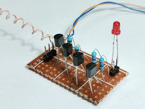
2N2222 devices used, but practically any junkbox NPN will do
Electromagnetic fields are everywhere, all around us. Some are generated naturally, but in vast majority of cases, it’s we humans that are generating them with artificial, electronic means. Everything from your mobile phone to the toaster will emit some sort of signal, be it intentional or not. So we think it only befits the general electronics-orientated hacker to have some way of sniffing around for these signals, so here is [Mirko Pavleski] with his take on a very simple pair of instruments to detect both static and dynamic electromagnetic fields.
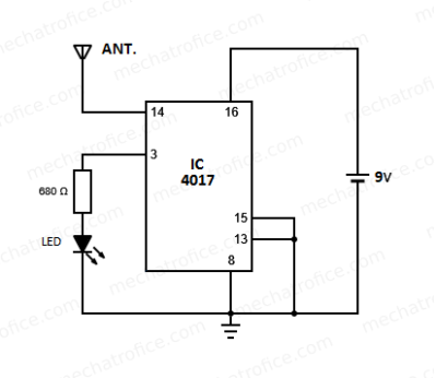
CMOS clock input connected directly to the antenna. Warning! ESD damage risk!
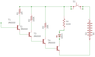
The first unit (a simple electroscope) uses a cascade of 2N2222 NPN bipolar transistors configured to give a high current gain, so any charge near the antenna will result in increasing currents in subsequent stages, finally illuminating the LED. Simple stuff.
The second unit relies on the extremely high input impedance of the old-school CMOS 4017 decade counter, which is likely of the order of 100 MΩ or even more. Normally you would not leave such a CMOS input floating, or even connect it with too long a PCB trace — lest it pick up a stray signal —but for detecting alternating EM fields, this appears to work just fine. Configured as a simple divide-by-ten, when presenting 50 Hz AC, the LED can be seen to flash at 5 Hz.
Simple stuff, and this scribe has all those exact parts in the junk box, so will be constructing these shortly!
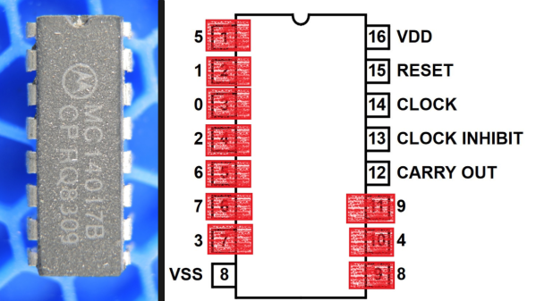
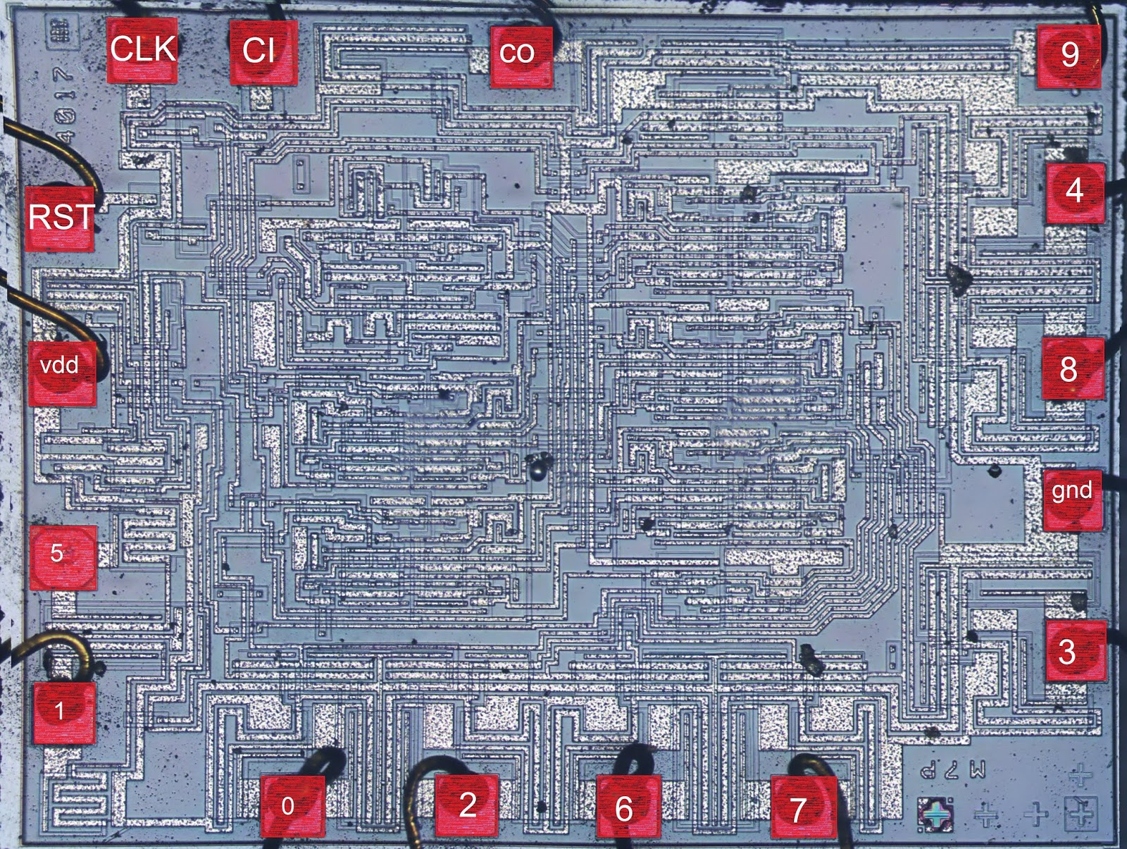
If you’ve ever handled a chip with a really strange or highly inconvenient pinout and suspected that the reason had something to do with the inner workings, you may be interested to see [electronupdate]’s analysis of why the 4017 Decade Counter IC has such a weirdly nonintuitive pinout. It peeks into an IC design dating from the 1970s to see an example of the kind of design issues that can affect physical layout.
In the case of the 4017, once decapped and the inner workings exposed, things became more clear. Inside the chip are a bunch of flip-flops and NAND gates, laid out in a single layer. Some of the outputs (outputs 5 and 1 for example, physically on pins 1 and 2 respectively) share the same flip-flop.
The original design placed the elements in a way that made the most logical sense for routing and layout, which resulted in nice and tidy inner workings but an apparently illogical pinout. A lot of this is probably feeling familiar to anyone who has designed and routed a single-layer PCB, where being limited to one layer makes it important to get the most connections as directly near one another as possible.
Chip design has of course come a long way since the 70s, but there is forever some level of trade-off to be made between outward tidiness and inner design harmony. The next time you’re looking at a part with an apparently illogical pinout, there’s a fair chance it makes far more sense on the inside.
Thanks to microcontrollers, RTC modules, and a plethora of cheap and interesting display options, digital clock projects have become pretty easy. Choose to base a clock build around a chip sporting a date code from the late 70s, though, and your build is bound to be more than run-of-the-mill.
This is the boat that [Fran Blanche] finds herself in with one of her ongoing projects. The chip in question is a Mostek MK50250 digital alarm clock chip, and her first hurdle was find a way to run the clock on 50 Hertz with North American 60-Hertz power. The reason for this is a lesson in the compromises engineers sometimes have to make during the design process, and how that sometimes leads to false assumptions. It seems that the Mostek designers assumed that a 24-hour display would only ever be needed in locales where the line frequency is 50 Hz. [Fran], however, wants military time at 60 Hz, so she came up with a circuit to fool the chip. It uses a 4017 decade counter to divide the 60-Hz signal by 10, and uses the 6-Hz output to turn on a transistor that pulls the 60-Hz output low for one pulse. The result is one dropped pulse out of every six, which gives the Mostek the 50-Hz signal it needs. Sure, the pulse chain is asymmetric, but the chip won’t care, and [Fran] gets the clock she wants. Pretty clever.
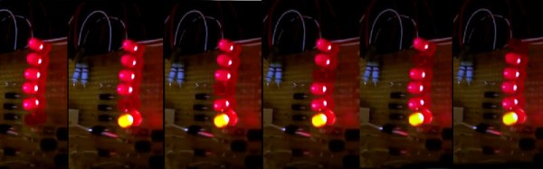
[Andrea De Napoli] created a LED display consisting of a half-dozen LEDs connected to the inverted signals of a CD4017 decade counter, giving the effect that a dark LED is running back and forth. The CD4017 works by activating 10 outputs, one at a time, as controlled by a clock signal sent to pin 14.
The first and last LEDs are lit by outputs 0 and 5 with the help of a PNP transistor and a 12K resistor. The middle four LEDs are switched by two outputs each and go dark when one of them goes high. [Andrea] really delves into the CD4017 and he shares a lot of detail in the project page.