Wearable Cone Of Silence Protects You From Prying Ears

Careful,  the walls have ears. Or more specifically, the smart speaker on the table has ears, as does the phone in your pocket, the fitness band on your wrist, possibly the TV, the fridge, the toaster, and maybe even the toilet. Oh, and your car is listening to you too. Probably.

How does one fight this profusion of listening devices? Perhaps this wearable smart device audio jammer will do the trick. The idea is that the MEMS microphones that surround us are all vulnerable to jamming by ultrasonic waves, due to the fact that they have a non-linear response to ultrasonic signals. The upshot of that is when a MEMS hears ultrasound, it creates a broadband signal in the audible part of the spectrum. That creates a staticky noise that effectively drowns out any other sounds the microphone might be picking up.

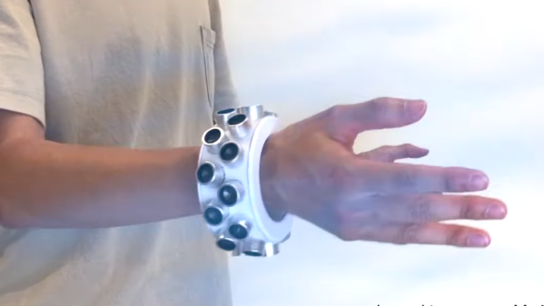
By why a wearable? Granted, [Yuxin Chin] and colleagues from the University of Chicago have perhaps stretched the definition of that term a tad with their prototype, but it turns out that moving the jammer around does a better job of blocking sounds than a static jammer does. The bracelet jammer is studded with ultrasonic transducers that emit overlapping fields and result in zones of constructive and destructive interference; the wearer’s movements vary the location of the dead spots that result, improving jamming efficacy. Their paper (PDF link) goes into deeper detail, and a GitHub repository has everything you need to roll your own.

We saw something a bit like this before, but that build used white noise for masking, and was affixed to the smart speaker. We’re intrigued by a wearable, especially since they’ve shown it to be effective under clothing. And the effect of ultrasound on MEMS microphones is really interesting.

Continue reading “Wearable Cone Of Silence Protects You From Prying Ears”

What Does Your Necklace Say?

If we write about sound reproduction, there is a good chance we found a home-made amplifier or an upcycled speaker system. In this case, you don’t use your ears to appreciate the sound; you use your hands or eyes. [ElatisEagles] converted an amplitude sound graph into a wearable bead. Even without much background it should be immediately recognizable for what it is. Presumably, they converted a sound wave to vectors, then used the “Revolve” function in Rhino, their software of choice. Sometimes this is called a “lathe” function. Resin printers should be able to build these without supports and with incredible fidelity.

Some tattoos put a sound wave on the skin, and use an app to play it back, but if you want to wear a sound bite from your favorite show and not get branded as the “Pickle Rick” gal/guy at the office, maybe swap out the color and sound wave before it goes stale. We would wear a bead that says, “drop a link in our tip line,” but you can probably think of something more clever.

We have other high-tech ornamentation that leverages motion instead of sound, or how about a necklace that listens instead.

Continue reading “What Does Your Necklace Say?”

Cable Operated Blast Door Needs No Power

Every well-equipped wood shop has a dust collection system, with blast gates at every tool to direct the suction power where you need it. If these gates are hard to reach they can be real pain to operate. [Cosmas Bauer] had this problem with his table saw, and created a convenient cable-operated mechanism.

The dust chute on table saw is on the back end, meaning he needs to walk around it to open it, and then walk back to the front to operate the machine. As we all know, laziness increased efficiency can be an excellent reason for projects. Electronics or pneumatics might get the job done, but [Cosmas] realised that a mechanical system might be simpler and more reliable.  Being a woodworker, he built most of the system out of wood.

The blast door itself is held in the closed position by a piece of elastic tubing. To pull it open, he attached a bicycle cable to the blast door, with the other side attached to a latching mechanism that is the star of the show. It’s a rotating disc, with the end of the cable and operating handle attached on the outer edge. A slot track is cut in the disc, in which a pin on the end of a short arm slides. It has a few sharp corners in the track, which forces the pin to only go around in one direction, and to latch in two possible positions when released. Check out the video after the break to see it in action.

Continue reading “Cable Operated Blast Door Needs No Power”

Sherbet Custom Game Pad Is Smooth And Sweet

When [Billiam]’s beloved Logitech G13 game pad went to that great spectate room in the sky, he decided to pay homage by designing a custom, more ergonomic replacement from the desk up. Grab a spoon and dig into the story of [Billiam]’s journey toward Sherbet, because it’s a sweet ride.

Here’s the scoop: like a lot of DIY game pads and keyboards, Sherbet is based on the Teensy. We often see the micro USB coming straight off the Teensy, especially in clear acrylic builds, but [Billiam] added a USB breakout board so there’s no direct stress on the Teensy itself.

One of [Billiam]’s design challenges comes from the game pad placement — he has a tall desk and uses a keyboard tray, so it has to fit the space and leave enough room for his hand. Fortunately, there are low-profile mechanical switches out there, although the keycap options are strongly limited. We love that [Billiam] embedded a tiny ceramic bearing into one of them to use as a homing bump, because that’s a great idea.

If you want to take a crack at this project, [Billiam] has all the goodies laid out. [Billiam] wanted to use QMK firmware, but they didn’t have joystick support yet, so he’s got an Arduino sketch running in the meantime.

We love a good custom game pad around here, especially if they can reprogram themselves.

Transparent LCD Makes Everything Look Futuristic

According to [Kelsey], transparent displays are guaranteed to make “everything feel like the future.” Unfortunately they’re hard to find, and the ones typically available are OLED and can’t make solid black colors. But as luck would have it, it’s possible to repurpose a common LCD to be sort of transparent.

A LCD uses nematic crystals that can polarize light, with the amount of polarization changing based on the electric field applied to the crystal. Light enters the front of the panel through a polarizing film, passes through the display, and then bounces off a reflective back coating. The display itself usually polarizes light in a way that matches the front polarizer. That means if you do nothing you get reflected light. However, if a part of the LCD gets an electric field, it will repolarize in such a way as to block the reflected light making the display look black in that area.

[Kelsey’s] trick is to peel off the reflector and replace it with polarizing film taken from another display. The new polarizer needs to be bigger than the display for one reason: you need to match the polarizing angle of the front film with the new back film. That means if the new film is exactly the right size, it won’t be able to rotate without leaving gaps. By starting with a larger piece, you’ll be able to rotate for maximum transparency before you stick it on.

We’ve seen some homemade transparent numeric displays. The transparent wood, though, has usually left something to be desired.

Why Some Chips Have Inconvenient Pinouts

If you’ve ever handled a chip with a really strange or highly inconvenient pinout and suspected that the reason had something to do with the inner workings, you may be interested to see [electronupdate]’s analysis of why the 4017 Decade Counter IC has such a weirdly nonintuitive pinout. It peeks into an IC design dating from the 1970s to see an example of the kind of design issues that can affect physical layout.

Inside the 4017. Want to make sense of how lines and shapes on a silicon wafer make an IC work? With the right teachers, it’s simple.

In the case of the 4017, once decapped and the inner workings exposed, things became more clear. Inside the chip are a bunch of flip-flops and NAND gates, laid out in a single layer. Some of the outputs (outputs 5 and 1 for example, physically on pins 1 and 2 respectively) share the same flip-flop.

The original design placed the elements in a way that made the most logical sense for routing and layout, which resulted in nice and tidy inner workings but an apparently illogical pinout. A lot of this is probably feeling familiar to anyone who has designed and routed a single-layer PCB, where being limited to one layer makes it important to get the most connections as directly near one another as possible.

Chip design has of course come a long way since the 70s, but there is forever some level of trade-off to be made between outward tidiness and inner design harmony. The next time you’re looking at a part with an apparently illogical pinout, there’s a fair chance it makes far more sense on the inside.

If any of you are interested in decapping ICs yourselves to see what’s inside, we saw that it’s possible with commonly available chemicals, not just nasty ones.

Continue reading “Why Some Chips Have Inconvenient Pinouts”

Electrification Of A Cheap Bead Roller

We all have old projects which maybe didn’t quite deliver knocking about, sometimes they gather dust for years. They have a use though, in that when you *really* need that part you can lift it from that forgotten project. That’s what [Mustie1] did with a forgotten electric bicycle project, he took its motor and used it to automate his bead roller.

A bead roller is a tool used in the world of automotive bodywork to press a bead — a continuous depression — into a piece of sheet metal. The inexpensive roller he had fitted in a bench vice, and was operated by means of a handle. Unfortunately the size of the tool meant that it was difficult to operate at the same time as rolling a precise bead, so improvement was required.

He first considered using a cordless drill, but then remembered the electric bicycle project. Its geared motor had come from an electric wheelchair and certainly possessed the right speed, but he needed a suitable sprocket. This was supplied from a scrap engine-assisted bicycle that he’d acquired, and proved to be perfect for the job. The final automated roller used the trigger controller from a cordless drill mounted in a foot switch, and the roller mounted on a stand repurposed from a piece of gym equipment. The result is a useful, and above all controllable, tool that can run a perfect bead in any shape desired on a piece of sheet metal.

Surprisingly this is the first bead roller we’ve featured here, but sheet metal work is a constant in hardware hacker projects. Read our guide to sheet metal bending, for a start.

Continue reading “Electrification Of A Cheap Bead Roller”