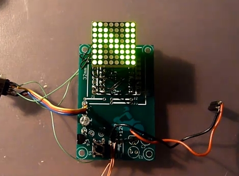
Gear Indicator For Suzuki Motorcycle

This little board serves as a current gear indicator for a motorcycle. It was designed with the Suzuki V-Storm motorcycles in mind as they have a sensor built into the gearbox. Other gear indicators rely on sensors on the shifters themselves, but reading the voltage level from a gearbox sensor gives much more reliable information.

The voltage measurement is handled by an ATmega88 microcontroller which in turn drives the 8×8 LED display. Also built into the system is a temperature sensor and photoresistor. The firmware takes advantage of both of these inputs, displaying temperature when in sixth gear or at the push of a button, and dimming the display based on ambient light. There are also settings for screen rotation, and user preferences.

We didn’t find schematics or software but this should be pretty easy to replicate. If you need a primer for AVR programming we’ve got you covered.

[Thanks Michal]

FPSLIC Powered LED Matrix

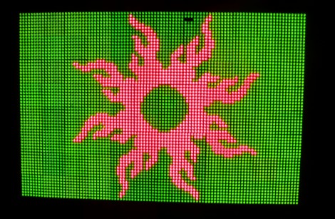
[Mathieu] built this display in hopes that he can play pong on it. You can imagine the headache that awaits when trying to figure out how to drive the 6144 bi-color LEDs. I must have worked out because the thing looks great in the video after the break. The solution he chose was a bit unfamiliar to us though. He used a Field Programmable System Level Integrated Circuit produced by Atmel, or FPSLIC. This is a kind of mash-up of components we’re more accustomed to.

The AT94K is a single chip that houses an 8-bit AVR microcontroller, and FPGA, and SRAM. This project uses that FPGA to handle the multiplexing of the display via code written in VHDL. The AVR core receives data via a USB port, stores two images in the SRAM (one for each LED color), and then outputs it to be drawn on the display. On second thought, this project sounds like fun and it’s a great way to get start learning that VHDL you’ve been putting off. Continue reading “FPSLIC Powered LED Matrix”

Great Interactive LED Puzzle

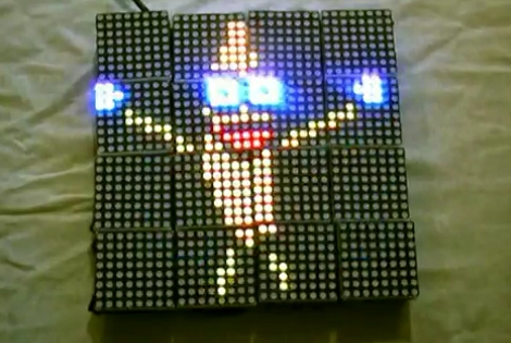
The GLIP project takes the delight of blinking LEDs and combines it with the ingenuity of modular communications. This takes the Puzzlemation concept a few steps further. In that project the modules were programmed through a base station and could be removed and used as a puzzle from there. The GLIP project uses a master block that you can see tethered in the photo. But the blocks communicate with each other via an infrared protocol. This way they can be continuously updated as they are place next to each other. Each module includes an STM32F105 ARM Cortex-M3 processor, quite a punch for the little blocks. Take a look at what they can do after the break.

Continue reading “Great Interactive LED Puzzle”

Wire-wrapping An LED Matrix

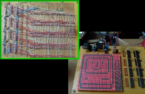
Regular reader [Osgeld] built a 1024 LED display matrix. This is a proof-of-concept design and he admittedly has overloaded the components. Most notably, the 595 shift registers (featured over the weekend) are sourcing too much current if all eight pins are active. That’s easy enough to fix in the next design by moving up to cascading LED drivers. Instead of soldering every connection in the display, [Osgeld] soldered the components in place and then used wire wrapping to make the point-to-point connections. This must have saved him a ton of time and frustration. We can’t wait to see what comes out of this first prototype.

Laser Command Game Uses Laser For Control

[vimeo=http://vimeo.com/10819322]

[Eliji Hayashi’s] project for a class at Carnegie Mellon University is absolutely delightful! It is a game he calls Laser Command because a laser pointer is used as the gaming controller. An 8×8 LED matrix serves as the display, but is also used as an 8×8 light sensor, much the same way as the LED advent project did. The display is rapidly switched between producing light and sensing it. The laser is bright enough that it becomes easy to pick up the voltage generated within the matrix during the sensing periods. The game is programmed on an Arduino mini and the whole thing wraps up into an incredibly small package. Brilliant.

[Thanks Juan]

LEDs Invade Coffee Table Crevice

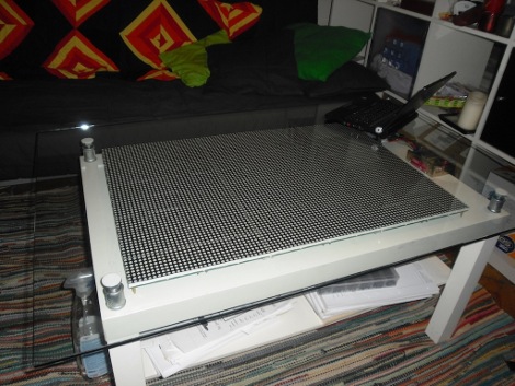
That’s a lot of LEDs, and a little bit of glass cleaner. [Tobias] spiced up his IKEA coffee table by adding 6144 LEDs. This is a larger realization of SparkFun’s LED coffee table which used 64 8×8 modules. [Tobias] sourced three display boards from Sure Electronics for a total of 96 8×8 modules. These boards are addressed through a serial interface; four serial lines for each board but a shared data bus for each of the row select pins and the data/latch/clock pins.  This method uses 19 of the 20 pins on the Arduino that drives the display. After the break you can see a demonstration. If this is more than you need there’s always the 112-LED and 81-LED table projects that can produce a full color range. Continue reading “LEDs Invade Coffee Table Crevice”

Update: Most Interesting Game In 64 Pixels

[Brad] has continued working on the Super Pixel Bros game. We saw a glimpse of this a few months ago but he’s added a lot since then. The game now has enemies; one type is similar to Bullet Bill, another type drops from the sky and walks toward you, kind of like a Goomba. Game play is quite responsive and it’s amazing what he has accomplished with such low resolution. In the video after the break [Brad] mentions that a friend is working on sound effects for jumps and block breaking. We’re assuming that the audio track in the background is already coming from the LEDBOY speaker.

Which reminds us, if you haven’t checked out the hardware, do so now. That enameled wire mess makes us shudder just a bit. There many be a kit version coming that will save you the point-to-point soldering madness. If that’s part of the fun for you keep an eye out for the forthcoming release of the hardware schematics.

Continue reading “Update: Most Interesting Game In 64 Pixels”