Building A GPS Receiver From The Ground Up

One of the more interesting facets of GPS is that, at least from the receiver’s point-of-view, it’s a fairly passive system. All of the information beamed down from the satellites is out in the ether, all the time, free for anyone on the planet to receive and use as they see fit. Of course you need to go out and buy a receiver or, alternatively, possess a certain amount of knowledge to build a circuit that can take those signals and convert them into something usable. Luckily, [leaning_tower] has the required knowledge and demonstrates it with this DIY GPS receiver.

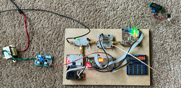
This receiver consists of five separate circuit boards, all performing their own function. The first, a mixer board, receives the signal via an active antenna and converts it to a lower frequency. From there it goes to a second mixer and correlation board to compare the signal to a local reference, then a signal processing board that looks at this intermediate frequency signal to make sense of the data its seeing. Finally, an FPGA interfacing board ties everything together and decodes the information into a usable form.

Dealing with weak signals like this has its own set of challenges, as [leaning_tower] found out. The crystal oscillator had to be decapped and modified to keep from interfering with the GPS radio since they operated on similar frequencies. Even after ironing out all the kinks, the circuit takes a little bit of time to lock on to a specific satellite but with a second GPS unit for checking and a few weeks of troubleshooting, the homebrew receiver is up and running. It’s an impressive and incredibly detailed piece of work which is usually the case with sensitive radio equipment like GPS. Here’s another one built on a Raspberry Pi with 12 channels and a pretty high accuracy.

Directional Antenna Stands Tall

When you think of directional ham radio antennas, you probably think of a Yagi, cubical quad, or a log-periodic antenna. These antennas usually are in a horizontal configuration up on a high tower. However, it is possible to build beams with a vertical orientation and, for some lower frequencies, it is far more practical than mounting the elements on a boom. [DXCommander] shows us his 40 meter two-element vertical antenna build in the video below.

A typical Yagi is just a dipole with some slightly longer or shorter elements to direct or reflect the signal. A normal vertical, however, is nothing more than half of a dipole that uses the ground as the other half. So it is possible to create reflectors and directors with a vertical-driven element.

Continue reading “Directional Antenna Stands Tall”

DIY Loading Coil Shortens Antenna Lengths

A newly licensed amateur radio operator’s first foray into radios is likely to be a VHF or UHF radio with a manageable antenna designed for the high frequencies in these radio bands. But these radios aren’t meant for communicating more than a double-digit number of kilometers or miles. The radios meant for long-distance communication use antennas that are anything but manageable, as dipole antennas for the lowest commonly used frequencies can often be on the order of 50 meters in length. There are some tricks to getting antenna size down like folding the dipole in all manner of ways, but the real cheat code for reducing antenna size is to build a loading coil instead.

As [VA5MUD] demonstrates, a loading coil is simply an inductor that is placed somewhere along the length of the antenna which makes a shorter antenna behave as a longer antenna. In general, though, the inductor needs to be robust enough to handle the power outputs from the radio. There are plenty of commercial offerings but since an inductor is not much more than a coil of wire, it’s entirely within the realm of possibility to build them on your own. [VA5MUD]’s design uses a piece of PVC with some plastic spacers to wind some thick wire around, and then a customized end cap with screw terminals attached to affix the antenna and feedline to. Of course you’ll need to do a bit of math to figure out exactly how many turns of wire will be best for your specific situation, but beyond that it’s fairly straightforward.

It’s worth noting that the coil doesn’t have to be attached between the feedline and the antenna. It can be placed anywhere along the antenna, with the best performance typically being at the end of the antenna. Of course this is often impractical, so a center-loaded coil is generally used as a compromise. Coils like these are not too hard to wind by hand, but for smaller, lower-current projects it might be good to pick up a machine to help wind the coils instead.

Continue reading “DIY Loading Coil Shortens Antenna Lengths”

A Canned Ham Ham Antenna

If you’d have asked us for odds on whether you could successfully turn a canned ham into an amateur radio antenna, we’d have declined the offer. Now, having seen [Ben Eadie (VE6SFX)]’s “hamtenna” project, we’d look at just about any “Will it antenna?” project with a lot less skepticism than before.

To be painfully and somewhat unnecessarily clear about [Ben]’s antenna, the meat-like product itself is not in the BOM for this build, although he did use it as sustenance. Rather, it was the emptied and cleaned metal can that was the chief component of the build, along with a few 3D printed standoffs and the usual feedline and connectors. This is a slot antenna, a design [Ben] recently experimented with by applying copper foil tape to his car’s sunroof. This time around, the slot was formed by separating the top and bottom of the can using the standoffs and electrically connecting them with a strip of copper tape.

Connected to a stub of coax and a BNC connector, a quick scan with a NanoVNA showed a fantastic 1.26:1 SWR in the center of the 70-cm ham band, and a nearly flat response all the way across the band. Results may vary depending on the size of canned ham you sacrifice for this project; [Ben]’s can measured just about 35 cm around, a happy half-wavelength coincidence. And it actually worked in field tests — he was able to hit a local repeater and got good signal reports. All that and a sandwich? Not too shabby.

Continue reading “A Canned Ham Ham Antenna”

Pocketable Yagi Antenna Really Shoots For Distance

For amateur radio operators, the quest for the perfect antenna never seems to end. Perhaps that’s because our requirements are always changing. We never quite seem to get to one design that can do everything. This copper-foil Yagi antenna might not do everything, but it really seems to tick off the boxes for gain and directionality along with ultra-portability.

If you’ve been following [Ben Eadie (VE6SFX)]’s trip down the rabbit hole of lightweight antenna building, you’ll recall that he’s already knocked off a J-pole antenna and a stealthy mobile slot antenna using little more than copper foil tape. Both of those designs performed great, but [Ben] had bigger fish to fry: he wanted to build a directional antenna for the 2-meter band and go for distance. The traditional Yagi-Uda is generally the preferred design for beam antennas, but they tend to be bulky and cumbersome. But with a roll of copper foil tape [Ben] was able to lay out a three-element Yagi on a sheet of Tyvek wrap. Reinforced with some packing tape and stiffened with a couple of fiberglass rods attached to a 3D printed handle, and it was ready to go.

[Ben]’s field test results were most impressive. Not only was he able to open up repeaters up to 90 km away, but he was getting good signal reports to boot. He was even able to reach a repeater 150 km distant, just barely though. Still, that’s mighty impressive performance from something that looks like a Union Jack and rolls up to fit in a pocket.

Continue reading “Pocketable Yagi Antenna Really Shoots For Distance”

Paperless RFID Tags Are Carbon-Based

RFID tags are great little pieces of technology, but unfortunately, the combination of paper, metal, and silicon means they are as bad as some modern pregnancy tests — single-use electronic devices that can’t be recycled.

Some prototypes of the RFID tags.

A team of design program graduates from London’s Royal College of Art aim to change that. They’ve devised a mostly-paper RFID tag that’s as safe to recycle as a piece of paper with a pencil doodle on it.

The team’s startup, PulpaTronics have created a design that uses paper as its only material. The circuitry is marked on the paper with a laser set to low power, which doesn’t burn or cut the paper, but instead changes to composition to be conductive.

PulpaTronics were also able to create a chip-less RFID tag much the same way, using a pattern of concentric circles to convey information. The company estimates that these tags will reduce carbon dioxide emissions by 70%, when compared with traditional RFID tags. They’ll also cost about half as much.

RFID is used in many industries, but it’s also great for hacking. Here’s an 8-track player that harnesses the power of RFID tags to play songs off of an SD card.

Thanks for the tip, [gir.st]!

Atomic Antenna Uses Lasers

If you think about it, an antenna is nothing more than a radio frequency energy sensor, or — more precisely — a transducer. So, it shouldn’t be a surprise that there could be different ways to sense RF that would work as an antenna. A recent paper in Applied Physics Letters explains an atomic antenna comprised of a rubidium vapor cell.

The interesting thing is that the antenna has no electrical components in the antenna, and can be located far away from the actual receiver. Instead of coax cables, the signal is read with a laser.

Continue reading “Atomic Antenna Uses Lasers”