A small PCB with an OLED screen showing a Dinosaur Game

Hackaday Prize 2022: RunTinyRun Is A Fully Solar-Powered, Portable Dinosaur Game

Fully solar-powered handheld gadgets have so far mostly been limited to ultra-low power devices like clocks, thermometers and calculators. Anything more complicated than that will generally have a battery and some means to charge it. An entirely solar-powered video game console is surely out of reach. Or is it? As [ridoluc] shows, such a device is actually possible: the RunTinyRun gets all its power directly from the Sun.

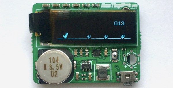
To be fair, it’s not really a full-fledged game console. In fact it doesn’t even come close to the original Game Boy. But RunTinyRun is a portable video game with an OLED display that’s completely powered by a solar panel strapped to its back. It will run indefinitely if you’re playing outside on a sunny day, and if not, letting it charge for a minute or two should enable thirty seconds of play time.

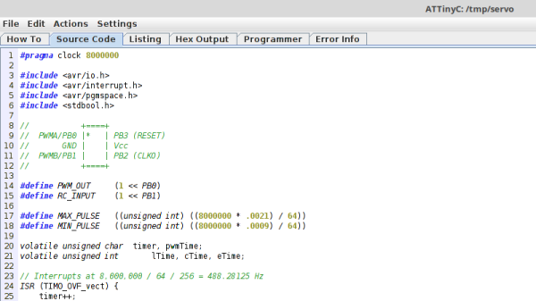
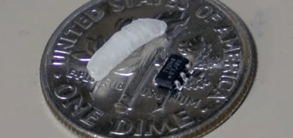
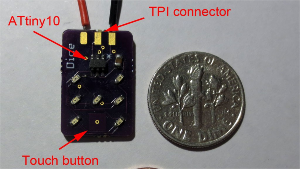
The game it runs is a clone of Google’s Dinosaur Game, where you time your button presses to make a T-Rex jump over cacti. As you might expect, the game runs on an extremely minimalist hardware platform: the main CPU is an ATtiny10 six-pin micro with just 1 kB of flash. The game is entirely written in hand-crafted assembly, and takes up a mere 780 bytes. A 0.1 farad supercap powers the whole system, and is charged by a 25 x 30 mm2 solar cell through a boost converter.

RunTinyRun is a beautiful example of systems design within strict constraints on power, code size and board area. If you’re looking for a more capable, though slightly less elegant portable gaming console, have a look at this solar-powered Game Boy.
A Dinosaur Game implementation running on a breadboard setup

A HVTPI adapter plugged into a USBASP, with a an IDC10 cable plugged into it in turn

HVTPI Primer And Toolkit Equips You For BOM Substitutions

Novel programming interfaces for MCUs might catch us by surprise, but then we inevitably get up to speed with the changes required. Today’s bastion is HVTPI – a “12V reset” addition to the TPI we’ve just started getting used to, and [Sam Ettinger] has shared a simple circuit to teach us all about it, along with PCB files and detailed explanations of how it all works.

HVTPI is an add-on on top of TPI, for which, as Sam explains, you need to hold RST at 12V when TPI would have it be low logic level, and leave it at Vtarget otherwise. For that, he has designed a variety of interposer boards of various complexity and requirements; explaining the choices behind each one and clearing up any misunderstandings that might occur on your way. All of the board files (and the TPI write-up copy) are caringly shared with us in a git repository, too! As a result, if you have an USB-ASP or an Arduino available, now you also have everything to do HVTPI, thanks to Sam’s work and explanations.

We’ve been covering Sam’s exploits before, and can’t help but be grateful for the stop-and-explain detour along the way. HVTPI being used on very small ATTiny parts, we wonder if something new in the vein of his recent FPC board able to fit and function entirely within a Type-C cable end!

With chip shortages, investigating programming interfaces for small and obscure yet in-stock microcontrollers has been, quite literally, paying off, and if you got some projects that need a MCU but won’t consume a whole lot of resources, it could be time to give an ATTiny10 a go. What’s the worst that can happen – you make the smallest chiptunes ever?

Jumbo LEDs Make For A Handy ATtiny Beacon

Inspiration can come from anywhere. Sometimes it’s just a matter of seeing an interesting part that you want to fiddle around with badly enough that you end up developing a whole idea, and potentially product, around it. That’s how [Bobricius] found himself creating this very slick little warning beacon, and looking at the end result, we think he made the right decision.

The Kingbright DLC-6SRD “jumbo” LED is actually six individual emitters built into a plastic diffuser. Interfacing with the device is simple enough; each LED has its normal anode and cathode leg, all you need to do is power them up. What [Bobricius] has created is a simple PCB design that the DLC-6SRD can plug right into, complete with a 2032 coin cell holder on the opposite side.

Of course, just lighting up all six elements at the same time wouldn’t be very interesting. [Bobricius] is controlling them individually right off of the digital pins of an ATtiny10 with the help of some Charlieplexing. This makes all kinds of interesting patterns possible, and as demonstrated in the video after the break, the current iteration of the project uses some very simple code to “rotate” the LED as if it was the flasher on an emergency vehicle.

The addition of a few blinking LEDs can make a world of difference in terms of nighttime visibility, so a cheap stick-on module that adds such a distinctive light pattern could be a very important safety device. It could also be useful for UAVs, following the FAA’s new rules which would mandate anti-collision lights for night flying.

Continue reading “Jumbo LEDs Make For A Handy ATtiny Beacon”

A Tiny IDE For Your ATtiny

When writing code for the ATtiny family of microcontrollers such as a the ATtiny85 or ATtiny10, people usually use one of two methods: they either add support for the chip in the Arduino IDE, or they crack open their text editor of choice and do everything manually. Plus of course there are the stragglers out there using Eclipse. But [Wayne Holder] thinks there’s a better way.

The project started out as a simple way for [Wayne] to program the ATtiny10 in C under Mac OS, but has since evolved into an open source, cross-platform integrated development environment (IDE) for programming a wide range of ATtiny chips in C, C++, or Assembly. Not only does it integrate the source code editor and programmer, but it even bundles in documentation for common variants of the chips including block diagrams and pinouts; making it a true one-stop-shop for ATtiny hacking.

His IDE runs under Java, including OpenJDK, and [Wayne] provides a stable pre-built executable for those who don’t want to clone the whole GitHub repository. He’s included the GNU/AVR toolchains, though notes that testing so far has been limited to Mac OS, and he’s interested in feedback from Windows and Linux users. Assembly is done either with GNU AVR-AS, or an assembler of his own design, though the latter is currently limited to the ATTiny10.

To actually get the code onto the chip, the IDE supports using the Arduino as a programmer as well as dedicated hardware like the BusPirate or the USBasp. If you go the Arduino route, [Wayne] has even come up with a little adapter board which he’s made available through OSH Park to help wrangle the diminutive chips.

The ATtiny10 might have something of a learning curve, but in exchange this family of tiny microcontrollers offers an incredible amount of capability. When you’re working with what’s essentially a programmable grain of rice, the only limit is your own creativity.

Ben Heck Can Program The Smallest Microcontroller

Microcontrollers are small, no one is arguing that. On a silicon wafer the size of a grain of rice, you can connect a GPS tracker to the Internet. Put that in a package, and you can put the Internet of Things into something the size of a postage stamp. There’s one microcontroller that’s smaller than all the others. It’s the ATtiny10, and its brethren the ATtiny4, 5, and 9. It comes in an SOT-23-6 package, a size that’s more often seen in packages for single transistors. It’s not very capable, but it is very small. It’s also very weird, with a programming scheme that’s not found in other chips from the Atmel/Microchip motherbrain. Now, finally, we have a great tutorial on using the ATtiny10, and it comes from none other than [Ben Heck].

The key difference between the ATtiny10 and other AVRs is that the tiny10 doesn’t use the standard AVR ISP protocol for programming. Instead of six pins for power, ground, MISO, MOSI, SCK, and RST, this is a high-voltage programming scheme that needs 12 Volts. The normal AVR programmer can do it, but you need to build an adapter. That’s exactly what [Ben] did, using a single-sided perf board, a lot of solder, and some headers. It looks like a lot, but there’s really not much to this programmer board. There’s a transistor and an optocoupler. The only thing that could make this programmer better is an SOT-23 ZIF socket. This would allow bare tiny10s to be programmed without first soldering them to a breakout board, but ZIF sockets are expensive to begin with, and the prices on SOT-23 sockets are absurd.

Programming the device was a matter of loading Atmel Studio and going through the usual AVR rigamarole, but Ben was eventually able to connect a light sensor to the tiny10 and have it output a value over serial. This was all done on a device with only 32 Bytes of RAM. That’s impressive, and one of the cool things about the smallest microcontroller you can buy.

Continue reading “Ben Heck Can Program The Smallest Microcontroller”

USB Arduino Into AVR TPI Programmer

Turning an Arduino of virtually any sort into a simple AVR 6-pin ISP programmer is old hat. But when Atmel came out with a series of really tiny AVR chips, the ATtiny10 and friends with only six pins total, they needed a new programming standard. Enter TPI (tiny programming interface), and exit all of your previously useful DIY AVR programmers.

[Kimio Kosaka] wrote a dual-purpose TPI and ISP firmware for the ATmegaxxUn chips that are used as a USB-serial bridge on the Unos, and constitute the only chip on board a Leonardo or Micro. The catch? You’re going to have to do a little bit of fine-pitch soldering. Specifically, [Kosaka-san] wants you to get access to an otherwise obscured signal by drilling out a via. We’d do it just for that alone.

Continue reading “USB Arduino Into AVR TPI Programmer”

7 LED’s, 2 Pins – Beat That, Charlieplexing

[Tim]’s Dice10 is an exercise in minimalism. Building an electronic dice using an ATtiny10 with code that fits within 1kB is not too difficult. Charlieplexing the LED’s would have used three of the four available GPIO pins. [Tim] upped the game by using just two GPIO pins to drive the seven LED’s for the dice. A third GPIO is used as a touch button input. Besides the ATtiny and the LED’s, the only other component used is a capacitor across the supply inputs.

2 GPIO for 7 LED's
2 GPIO for 7 LED’s

The LED’s are grouped in three pairs of two LED’s and a single centre LED. Usually, Charlieplexed LED’s are connected across pairs of GPIO pins. But his scheme includes connections to the 5V and GND terminals, besides the two GPIO pins. Building a truth table makes it easy to figure out what’s going on.

STATE PB2 PB0 LED's
1     Z   Z   --
2     L   Z   LED 1/2
3     H   Z   LED 3/4
4     Z   L   LED 5/6
5     Z   H   --
6     H   L   LED9
7     L   H   --
8     H   H   --
9     L   L   --

Only the logic states used are listed in the table. It’s possible to add two more LED’s between PB0 and GND and one more anti-parallel with LED9, making a total of 10 LED’s driven by two pins. That’s quite a hack. The important thing here is to have two LED’s in series in the arms that connect to either 5V or GND.

[Tim] has posted  the code and hardware source files on his Github repo, and his blog post has some additional details on how he solved the problem.

If you’re looking for more inspirations on minimal dice designs, check this “PIC powered pair of electronic dice” which uses a PIC 12F629 with five outputs driving a pair of 7 pips to make a dual dice.

1kb-thumb

If you have a cool project in mind, there is still plenty of time to enter the 1 kB Challenge! Deadline is January 5, so check it out and fire up your assemblers!