A breadboard with a few DIP chips

Minimalist 6502 System Uses A CPU And Not Much Else

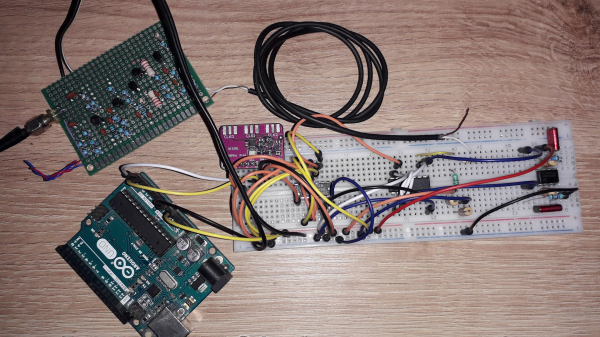
A central processing unit, or CPU, is the heart of any computer system. But it’s definitely not the only part: you also need RAM, ROM and at least some peripherals to turn it into a complete system that can actually do something useful. Modern microcontrollers typically have some or all of these functions integrated into a single chip, but classic CPUs don’t: they were meant to be placed on motherboards along with dozens of other chips. That’s why [c0pperdragon]’s latest project, the SingleBreadboardComputer, is such an amazing design: assisting its 6502 CPU are just four companion chips.

The entire system takes up just one strip of solderless breadboard. Next to the CPU we find 32 KB of SRAM, 32 KB of flash and a clock oscillator. The fifth chip is a 74HC00 quad two-input NAND gate, which is used as a very tiny piece of glue logic to connect everything together. Two of its NAND gates are used for address decoding logic, allowing either the ROM or RAM chip to be selected depending on the state of the CPU’s A15 line as well as blocking the RAM during the low phase of the system clock. The latter function is needed because the address lines are not guaranteed to be stable during the low phase and could cause writes to random memory locations.

The remaining two NAND gates are connected as an RS-flipflop in order to implement a serial output. This is needed because the CPU cannot keep its outputs in the same state for multiple clock cycles, which is required for a serial port. Instead, [c0pperdragon] uses the MLB pin, normally used to implement multiprocessor systems, to generate two-clock pulses, and stores the state in the flipflop for as long as needed. A few well-timed software routines can then be used to transmit and receive serial data without any further hardware.

Currently, the only software for this system is a simple demonstration that sends back data received on its serial port, but if you fancy a challenge you could write programs to do pretty much anything. You could probably find some inspiration in other minimalist 6502 boards, or projects that emulate a complete motherboard in an FPGA.

Simple Breadboard SDR For Shortwave

One of the best ways to learn about radios is to build your own, even in the age of cheap SDR dongles. [Aniss Oulhaci] demonstrates this with a simple HF SDR receiver built on a breadboard.

The receiver takes the form of a simplified Tayloe detector. An RF preamp circuit amplifies the signal from a shortwave antenna and feeds it into a 74HC4066D analog switch, which acts as a switching mixer. It mixes the input signal with the local oscillator’s I and Q signals to produce the intermediate frequency signals. The local oscillator consists of a SI5351 clock generator with a 74HC74D flip-flop to generate the I and Q pair. The signals pass through a low pass filter stage and get amplified by an LM358 op amp, resulting in the IQ signal pair being fed to a computer’s stereo sound card.

An Arduino is used to control the SI5351 clock generator, which in turn is controlled by the same program created for the SDR Shield. With the audio signal fed to HDSDR, [Aniss] was able to pick up a shortwave radio broadcaster.

While this is by no means a high-performance receiver, building an SDR on a breadboard is still a great weekend project, with plenty of potential for further experimentation.

Continue reading “Simple Breadboard SDR For Shortwave”

retro breadboard

Retro Breadboard Gives Up Its 1960s Secrets

When we see [Ken Shirriff] reverse engineering something, it tends to be on the microscopic level. His usual forte is looking at die photos of strange and obsolete chips and figuring out how they work. And while we love those efforts, it’s nice to see him in the macro world this time with a teardown and repair of a 1960s-era solderless breadboard system.

If you’d swear the “Elite 2 Circuit Design Test System” featured in [Ken]’s post looks familiar, it’s probably because you caught his partner-in-crime [CuriousMarc]’s video on the very same unit, an eBay score that arrived in non-working condition. The breadboard, which retailed for $1,300 in 1969 — an eye-watering $10,000 today — was clearly not aimed at the hobbyist market. Truth be told, we didn’t even know that solderless breadboards were a thing until the mid-70s, but live and learn. This unit has all the bells and whistles, including three variable power supplies, an array of switches, buttons, indicator lamps, and jacks for external connections, and a pulse generator as well as a legit function generator.

Legit, that would be, if it actually worked. [Ken]’s contribution to the repair was a thorough teardown of the device followed by reverse-engineering the design. Seeing how this thing was designed around the constraints of 1969 technology is a real treat; the metal can transistor and ICs and the neat and tidy PCB layout are worth the price of admission alone. And the fact that neon lamps and their drivers were cheaper and easier to use than LEDs says a lot about the state of the art at the time.

As for the necessary repairs, [Marc]’s video leaves off before getting there. That’s fine, we’re sure he’ll put [Ken]’s analysis to good use, and we always enjoy [Marc]’s video series anyway. The Apollo flight comms series was a great one, too. Continue reading “Retro Breadboard Gives Up Its 1960s Secrets”

8-bit counter made from 555s

555 Timer Contest Entry: A Digital Counter With Nothing But 555s

With a 555 on the BOM, you never know what you’re going to get. With 40 of the versatile timer chips in a build, you might just get something completely unexpected, like this 555-based eight-bit digital counter.

This one comes to us by way of [Astronomermike], who chose to make a digital circuit with nothing but 555s and a largish handful of passives as his entry in the current 555 Timer Contest. The ubiquitous timer chip is not exactly the first chip that comes to mind for digital applications, but it does contain an SR latch, which only requires a little persuasion to become a JK flip flop. His initial design for the flip flop that would form the core of the circuit had a pair of 555s surrounded with a bunch of OR gates and inverters — within the rules of the contest but hardly in its spirit. Luckily, the 555 makes a fine inverter too, and along with some diode-resistor OR gates, the basic counter module was born.

The video below shows the design and build, as well as the trip down the troubleshooting rabbit hole courtesy of a bad breadboard. Each half-nibble stage of the 8-bit counter occupies a full breadboard with ten 555s; the whole 40-chip string actually works and looks pretty cool doing it.

Truth be told, this is exactly the kind of thing we had in mind when dreaming up this year’s 555 contest, so good on [Astronomermike] for thinking outside the box for this one. To see what other uses people have found for the chip that keeps on giving, or to get your entry in before the deadline on January 10, head over to the contest page.

Continue reading “555 Timer Contest Entry: A Digital Counter With Nothing But 555s”

A Well Documented BreadBoard Computer Shows Dedication

These pages have not been exactly devoid of home-built computers, with those constructed on solderless breadboard less frequent, but still not rarities. But what is more of a rarity is this ground-up 8-bit 74xx logic-based computer (video, embedded below) with full source, an emulator, assembler and test suite. [JDH] spent a solid couple of weeks working late into the night to build this, and the results show for themselves.

The new JDH-8 is now a figment of reality.

The architecture is a traditional 8-bit load/store microcoded processor with the microcode stored in easily programmable AT28C64 EEPROMs for ease of tweaking.  The address bus is 16-bits, which is quite ample for this, and puts it in line with (admittedly more sophisticated) 8-bit micros of old such as the 6502. There is also a hardware stack, and a discrete-logic ALU as well! Finally, since that wasn’t enough work already, he added in his own discrete logic video controller.

Wise people simulate before prototyping something like this

There are sixteen instructions covering memory access, ALU operations and I/O operations. One of the great things about this project is that [JDH] readily admits the mistakes made along the way, and how the architecture didn’t need to be this complex. One example is that hardware stack wasn’t really necessary as it could just have been implemented in software. Also, due to the implementation, memory accesses were so fast compared with the achievable cycle time, that there really was no point to using load/store architecture at all! Still, [JDH] had fun building and programming it!

It was interesting to see the use of LogiSim-Evolution to debug first a high level model of the architecture and then the translation into TTL chips. This scribe wasn’t aware of that tool (the shame!) but is going to try this out real soon.

All code for the software side of things can be found on the project GitHub. Perhaps the hardware design will appear there as well, be at the time of writing we couldn’t seem to find it.

Can’t get enough breadboard computers? (We can’t) check this out from last year. Stuck for a suitable enclosure for your latest bread breadboard computer? How about a bread bin.

Continue reading “A Well Documented BreadBoard Computer Shows Dedication”

A breadboard filled with logic chips and wiring

SPAM-1 Is A Well-Documented Discrete CPU With An Impressive Software Library

Here at Hackaday we love projects that are so well-documented that you can spend days reading up on what the designer has achieved. [John Lonergan] didn’t disappoint when he designed the SPAM-1, an 8-bit CPU built from discrete logic gates. His detailed log contains a wealth of information on such things as designing opcodes, optimizing program counter logic, running a digital simulation, as well as his thoughts on microcode design. The sheer volume of it may be a bit off-putting to beginners, so it might be best to start with the video series that describes the architecture and goes into detail on several sub-blocks.

The design has changed a bit since [John] first started on the project, as he decided to add more and more features, but the final result is a well-thought out architecture that keeps the simplicity needed for discrete hardware but still has enough features to keep it interesting for seasoned CPU aficionados. The instruction size is rather large (48 bits) to simplify the instruction decoding at the expense of larger code size. Conditional jump instructions are not present; instead, all instructions have an optional control flag to make them conditional, a feature inspired by the ARM instruction set.

Once the design was mature enough, [John] modelled the entire thing in Verilog and simulated his design to verify correct operation and to check the timings, estimating it to be workable up to 5 MHz or so. A large stack of breadboards and DIP chips from the 74xx series then brought the design to life.

Not content with simply designing, simulating and implementing a custom CPU in hardware, [John] also spent significant effort on the software side of things, writing an assembler and even a C-like compiler for the SPAM-1 platform. And if that wasn’t enough, he also added an emulator for the classic CHIP-8 language, which allows it to run existing programs like Pong and Tetris. Input and output for all this software is mostly through a UART connection to a PC. A VGA interface is still on [John]’s to-do list, but he did build an adapter to connect a classic NES controller to the system.

The SPAM-1 is a worthy addition to the long list of discrete-logic CPUs we’ve seen here, such as this breadboard computer running a UNIX-like OS or this minimalistic one. If you’d like to see one that implements an existing instruction set, try this homebrew RISC-V computer.

Continue reading “SPAM-1 Is A Well-Documented Discrete CPU With An Impressive Software Library”

A breadboard full of chips

BreadBin Is An 8-bit TTL CPU On A Breadboard, In A Bread Bin

Building a CPU out of logic gates is a great way to learn about the inner workings of microprocessors, and we’ve seen several impressive projects in this area. [c0pperdragon] set himself the task of designing a very capable 8-bit CPU using just 74HC type logic chips on a large plug-in breadboard. To emphasize the “bread” theme, he put the whole thing inside an actual bread bin and named the accompanying software BERND after an anthropomorphic loaf from a German TV channel.

Getting a reliable breadboard big enough for the task at hand required some engineering by itself: cheap breadboards often have trouble making a reliable contact at each and every pin, while the length of the ground path and lack of shielding cause trouble for high-speed circuits. [c0pperdragon] therefore bought high-quality breadboards and soldered the ground wires together to get a proper low-resistance path. A ground plane made of aluminium foil should also help to prevent signal integrity issues.

A breadboard computer inside a wooden bread bin
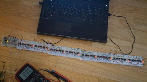
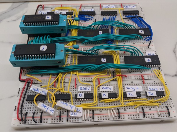
The total circuit is incredibly compact for a complete CPU, using just 33 chips. This includes 64 KB of flash to store programs as well as a 555 timer to generate a clock signal. I/Os are limited to simple eight-bit input and output buses, but a sixteen-bit address bus gives it plenty of space to add ROM, RAM or fancier interfaces.

The aforementioned BERND program is an emulator that allows the BreadBin to run code written for the 65C816 processor, the 16-bit CPU used in the Super Nintendo and the Apple IIGS. This makes it easy to re-use programs developed for [c0pperdragon]’s earlier OS816 system, which uses an actual 65C816 chip.

This has to be one of the cleanest breadboard CPU designs we’ve seen so far, certainly a lot cleaner than this one. If you’d like to watch a detailed guide to building an 8-bit CPU on a breadboard, we recommend this project.