A Simple Guide To Cams

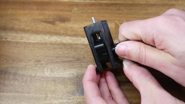
With the availability of precision controllable actuators, it’s easy to overlook the simple but versatile mechanisms that got us here. In the video after the break, [Teaching Tech] explores the basics of cams and how to use them in your projects.

Cams are used to convert rotation into linear motion, and are probably best known for their use in engines and locking mechanisms. [Teaching Tech] first goes over the basic design and terminology in CAD, and demonstrates it’s use with a cam follower, locking mechanism, cam plate, and a knob that snaps to predefined positions. Of course a cam shape is not limited to a single lobe, but can have multiple lobes of various heights to create different motion patterns.

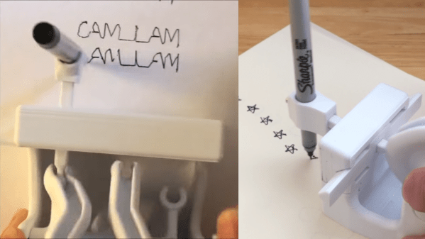
Cams are especially useful when you need to operate multiple mechanisms from a single input drive, as [Teaching Tech] demonstrates with the 3D printed automaton of a polar bear attempting to swipe a seal. We’ve also seen cams on a mechanical 7-segment display, and they were used to safely fire machine guns through aircraft propellers up to the 1950’s.

So next time you’re thinking adding another actuator to a project, take a moment to consider if a cheap and simple cam could do the job.

Continue reading “A Simple Guide To Cams”

Hand-Cranked Doodler Made Using A 3D Printer

3D printers are great at creating complex geometry out of plastic, and that geometry can often pull off some impressive tricks. [DaveMakesStuff] found a way to generate geometry that draws 2D shapes with a pen and some fancy cams, and it’s really fun to watch.

The build is relatively simple. It consists of a frame which holds a 3D-printed cam turned by a hand crank. That cam controls the movement of a pen in two dimensions, letting it draw all manner of shapes. Videos on Reddit demonstrate it drawing squares, figure eights, and stars, while on YouTube, it writes the phrase “CAM I AM.”

According to [DaveMakesStuff], he figured out how to create the cams with “hours and hours of tedious CAD work.” We imagine there’s a way to do this with maths instead in parametric modelling software, and await such a build on the Hackaday tipsline. Those eager to recreate the build can explore the files on Thingiverse.

We’ve seen some great 3D-printed mechanisms before, too, like this zig-zag cam for a sewing machine. Video after the break.

Continue reading “Hand-Cranked Doodler Made Using A 3D Printer”

Learning Through Play Hack Chat With Greg Zumwalt

Join us Wednesday at noon Pacific time for the Learning Through Play Hack Chat!

You may think you’ve never heard of Greg Zumwalt, but if you’ve spent any time on Instructables or Thingiverse, chances are pretty good you’ve seen some of his work. After a long career that ranged from avionics design and programming to video game development, Greg retired and found himself with the time to pursue pet projects that had always been on the back burner, including his intricate 3D-printed automata. His motto is “I fail when I decide to stop learning,” and from the number of projects he turns out and the different methods he incorporates, he has no intention of failing.

Please join us for this Hack Chat, where we’ll discuss:

  • Lifelong learning through play;
  • Toy-building as a means to skillset growth;
  • Sources of inspiration and getting new ideas; and
  • What sorts of projects Greg has in the pipeline.

You are, of course, encouraged to add your own questions to the discussion. You can do that by leaving a comment on the Learning Through Play Hack Chat and we’ll put that in the queue for the Hack Chat discussion.

join-hack-chatOur Hack Chats are live community events on the Hackaday.io Hack Chat group messaging. This week we’ll be sitting down on Wednesday, March 13, at noon, Pacific time. If time zones have got you down, we have a handy time zone converter.

Click that speech bubble to the right, and you’ll be taken directly to the Hack Chat group on Hackaday.io. You don’t have to wait until Wednesday; join whenever you want and you can see what the community is talking about.

Ten 3D Printed Gadgets That Just Can’t Stay Still

There was a time, not so very long ago, when simply getting a 3D printer to squirt out an object that was roughly the intended shape and size of what the user saw on their computer screen was an accomplishment. But like every other technology, the state of the art has moved forward. Today the printers are better, and the software to drive them is more capable and intuitive. It was this evolution of desktop 3D printing that inspired the recently concluded 3D Printed Gears, Pulleys, and Cams contest. We wanted to see what hackers and makers can pull off with today’s 3D printing tools, and the community rose to the challenge.

Let’s take a look at the top ten spinning, walking, flapping, and cranking 3D printed designs that shook us up:

Continue reading “Ten 3D Printed Gadgets That Just Can’t Stay Still”

7-Segment Display Is 3D Printed And Hand Cranked

[Peter Lehnér] has designed a brilliant 7-segment flip-segment display that doesn’t really flip. In fact, it doesn’t use electromagnets at all. This one is 3D printed and hand cranked. It’s a clever use of a cam system to set the segments for each digit (0-9) makes it a perfect entry in the Hackaday 3D Printed Gears, Pulleys, and Cams contest.

We find the nomenclature of these displays to be a bit confusing so let’s do a quick rundown. You may be most familiar with flip-dot displays, basically a dot-matrix grid of physical pixels that are black on one side and brightly colored (usually chartreuse) on the other. We saw a giant flip-dot display at CES four years ago. Akin to flip-dots are flip-segment displays which do the same thing but with segments of a digit rather than dots. We featured a 3D printed version of these last week. The common aspect of most flip displays is an electromagnet used to change the state of the dot or segment.

The version [Peter] designed gets rid of the magnets and coils, replacing them with mechanical logic instead. Each segment sits in a track on the frame of the digit. When slid to one position it is hidden by the bezel, in the other position it slides into view. A cleverly designed set of cams move the segments at each of 10 positions. The animated graphic here shows three cams which are responsible for moving just two of the segments. More cams are added to complete assembly, a process shown in the second half of the demo video found below.

We’re delighted to see this as an entry in the contest and can’t wait to see what kind of gear, cam, or pully scheme is built into your projects!

Continue reading “7-Segment Display Is 3D Printed And Hand Cranked”

New Contest: 3D Printed Gears, Pulleys, And Cams

One of the killer apps of 3D printers is the ability to make custom gears, transmissions, and mechanisms. But there’s a learning curve. If you haven’t 3D printed your own gearbox or automaton, here’s a great reason to take the plunge. This morning Hackaday launched the 3D Printed Gears, Pulleys, and Cams contest, a challenge to make stuff move using 3D-printed mechanisms.

Adding movement to a project brings it to life. Often times we see projects where moving parts are connected directly to a servo or other motor, but you can do a lot more interesting things by adding some mechanical advantage between the source of the work, and the moving parts. We don’t care if it’s motorized or hand  cranked, water powered or driven by the wind, we just want to see what neat things you can accomplish by 3D printing some gears, pulleys, or cams!

No mechanism is too small — if you have never printed gears before and manage to get just two meshing with each other, we want to see it! (And of course no gear is literally too small either — who can print the smallest gearbox as their entry?) Automatons, toys, drive trains, string plotters, useless machines, clockworks, and baubles are all fair game. We want to be inspired by the story of how you design your entry, and what it took to get from filament to functional prototype.

Continue reading “New Contest: 3D Printed Gears, Pulleys, And Cams”

Frickin’ Amazing Clock

Wwood_clock_05
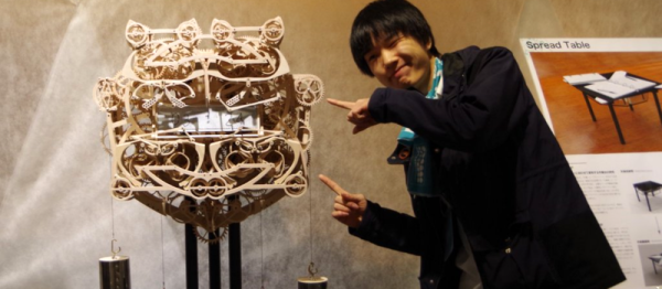
e’ve featured a lot of clock builds, but this one, as the title suggests, is frickin’ amazing. Talented art student [Kango Suzuki] built this Wooden Mechanical Clock (Google translation from Japanese) as a project while on his way to major in product design. There’s a better translation at this link. And be sure to check out the video of it in motion below the break.

[Kango]’s design brief was to do something that is “easy for humans to do, but difficult for machines”. Writing longhand fits the bill, although building the machine wasn’t easy for a human either — he needed six months just to plan the project.

The clock writes time in hours and minutes on a magnetic board. After each minute, the escapement mechanism sets in motion almost 400 wooden cogs, gears and cams. The board is tilted first to erase the old numbers, and then the new numbers are written using four stylii.

The clock doesn’t have any micro controllers, Arduinos, servos or any other electronics. The whole mechanism is powered via gravity using a set of four weights. [Kango] says his biggest challenge was getting the mechanism to write the numbers simultaneously. While he managed the geometry right, the cumulative distortion and flex in the hundreds of wooden parts caused the numbers to be distorted until he tuned around the error.

Continue reading “Frickin’ Amazing Clock”