Protect Vintage Gear With Easy Capacitor Reforming

Having acquired some piece of old electronic equipment, be it a computer, radio, or some test gear, the temptation is there to plug it in as soon as you’ve lugged it into the ‘shop. Don’t be so hasty. Those power supplies and analog circuits often have a number of old aluminium electrolytic capacitors of unknown condition, and bad things can happen if they suddenly get powered back up again. After a visual inspection, to remove and replace any with obvious signs of leakage and corrosion, those remaining may still not be up to their job, with the oxide layers damaged over time when sat idle, they can exhibit lower than spec capacitance, voltage rating or even be a dead short circuit. [TechTangents] presents for us a guide to detecting and reforming these suspect capacitors to hopefully bring them, safely, back to service once more.

Capacitor failure modes are plentiful

When manufactured, the capacitors are slowly brought up to operating voltage, before final encapsulation, which allows the thin oxide layer to form on the anode contact plate, this is an electrically driven chemical process whereby a portion of the electrolyte is decomposed to provide the needed oxygen ions. When operating normally, with a DC bias applied to the plates, this oxidation process — referred to as ‘self-healing’ — continues slowly, maintaining the integrity of the oxide film, and slowly consuming the electrolyte, which will eventually run dry and be unable to sustain the insulating oxide layer.

If left to sit un-powered for too long, the anodic oxide layer will decay, resulting in reduced operating voltage. When powered up, the reforming process will restart, but this will be in an uncontrolled environment, resulting in a lot of excess heat and gases being vented. It all depends on how thin the oxide layer got and if holes have started to form. That is, if there is any electrolyte left to react – it may already be far too late to rescue.

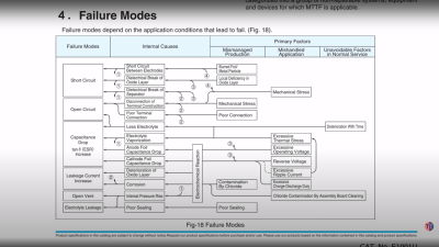
If the oxide layer is sufficiently depleted, the capacitor will start to conduct, with a resultant self-heating and runaway thermal decomposition. They can explode violently, which is why there are score marks at the top of the can to act as a weak point, where the contents can burst through. A bit like that ‘egg’ scene in Aliens!

Yucky leaky capacitor. Replace these! and clean-up that conductive goo too.

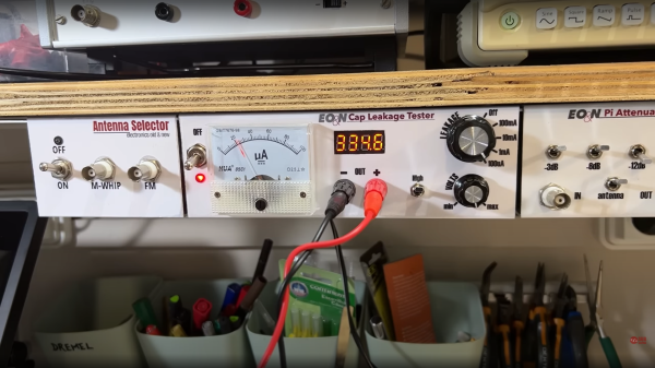
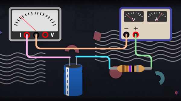
The ‘safe’ way to reform old capacitors is to physically remove them from the equipment, and apply a low, controlled voltage below the rated value to keep the bias current at a low value, perhaps just 2 mA. Slowly, the voltage can be increased to push the current back up to the initial forming level, so long as the current doesn’t go too high, and the temperature is within sensible bounds. The process ends when the applied voltage is at the rated value and the current has dropped off to low leakage values.

A word of warning though, as the ESR of the reformed caps could be a little higher than design, which will result in higher operating temperature and potentially increased ripple current in power supply applications.

We’re really glossing over this subject fast here, but [TechTangents] was kind enough to link to some fine capacitor-related reading for those who need a primer. Here is a US DoD handbook for reforming capacitors with advice on storage shelf life, some tech notes on using electrolytic capactors from chemi-con, and a general capacitor guide from TDK. Reforming caps is nothing new, here’s an previous article about repairs, and something a bit more recent.

Continue reading “Protect Vintage Gear With Easy Capacitor Reforming”

DIY capacitor leakage tester nestled among neighbours all mounted underneath a shelf

DIY Capacitor Leakage Tester With A Professional Finish

[Manuel Caldeira] has built a nice electronics work area that would be the envy of many, complete with an under-shelf rail of custom-built instruments that are specific to the needs of areas of electronics that [Manuel] is involved with. The highlighted project here is a capacitor leakage tester, which is very handy for sorting through piles of old parts looking for anything still within spec, or just verifying a part on a board is the culprit you suspect it is.

The thing is, certain types of capacitors have a limited life both in operation and in storage. Usually, we’re talking about electrolytics here, where the electrolyte solution can leak out or dry out, but also the passive oxide layer on the anode plate can deteriorate if the device is left unpowered for long periods — the oxide disintegrates, and the capacitor will start to leak current. Eventually, the breakdown can be bad enough for the capacitor to conduct so well that it overheats and the result can be a surprisingly violent experience. So, if you deal with capacitors a lot, especially electrolytics, then a leakage tester is a very good instrument to own.

We like [Manuel]’s construction method here, with custom PCBs nestled inside a simple bent aluminium enclosure. No need for a top or sides, as these, are intended to bolt underneath a shelf, and butt up against their neighbor. The front panel graphics are done in a simple but very effective manner, using printable sticker sheets, with a clear adhesive over-sheet. They certainly have a professional finish, and this is definitely a construction method worth considering.

For those a little unfamiliar with this important component, why not leap into some theory with this handy dive into the simple parallel plate capacitor? Next, may we suggest a little overview of the different capacitor types and how to best make use of them?

Continue reading “DIY Capacitor Leakage Tester With A Professional Finish”

Making Variable Capacitors By Stretching Aluminium Cans

Sometimes when you need a component, the best way to get it is by building it yourself. [North Carolina Prepper] did just that, creating his own trombone-style variable capacitor by stretching some aluminium beverage cans. 

The requirement was for a 26 pF to 472 pF capactitor, for a radio transmitting from 7 MHz to 30MHz. The concept was to use two beverage cans, one sliding inside the other, as a capacitor, with an insulating material in between.

To achieve this, a cheap exhaust-pipe expanding tool was used to stretch a regular can to the point where it would readily slide over an unmodified can, plus some additional gap to allow for a plastic insulating sheet in between. Annealing the can is important to stop it tearing up, but fundamentally, it’s a straightforward process.

The resulting trombone capacitor can readily be slid in and out to change its capacitance. The build as seen here achieved 33 pF to 690 pF without too much hassle, not far off the specs [North Carolina Prepper] was shooting for.

Radio hams are very creative at building their own equipment, especially when it comes to variable capacitors. Video after the break.

Continue reading “Making Variable Capacitors By Stretching Aluminium Cans”

Six Shooter Swaps Powder For Popped Capacitors

Modern firearms might seem far removed from the revolvers of the Old West, but conceptually, they still operate on the same principle: exploding gunpowder. But as anyone who has put too much voltage through an electrolytic capacitor knows, gunpowder isn’t the only thing that explodes. (Yes, it isn’t technically an explosion.)

[Jay Bowles] wondered if it would be possible to construct an electrically-fired weapon that used used a standard capacitor in place of the primer and powder of a traditional cartridge. While it would naturally have only the fraction of the muzzle velocity or energy of even the smallest caliber firearm, it would be an interesting look at an alternate approach to what has been considered a largely solved problem since the mid-1800s.

In his latest Plasma Channel video, [Jay] walks viewers through the creation of his unconventional pistol, starting with a scientific determination of how much energy you can get out of popped capacitor. His test setup involved placing a capacitor and small projectile into an acrylic tube, and noting the relation between the speed of the projectile and the voltage passed through the cap. At 30 VDC the projectile would reliably fire from the barrel of his makeshift cannon, but by tripling the voltage to 90 VDC, he noted that the muzzle velocity saw the same 3X improvement.

Continue reading “Six Shooter Swaps Powder For Popped Capacitors”

Building A Spot Welder From 500 Junk Capacitors

[Kasyan TV] over on YouTube was given a pile of spare parts in reasonably large quantities, some of which were useful and allocated to specific projects, but given the given the kind of electronics they’re interested in, they couldn’t find a use for a bag of 500 or so low specification 470uF capacitors. These were not low ESR types, nor high capacitance, so unsuitable for power supply use individually. But, what about stacking them all in parallel? (video, embedded below) After a few quick calculations [Kasyan] determined that the total capacitance of all 500 should be around 0.23 Farads with an ESR of around 0.4 to 0.5 mΩ at 16V and packing a theoretical energy total of about 30 joules. That is enough to pack a punch in the right situation.

A PCB was constructed to wire 168 of the little cans in parallel, with hefty wide traces, reinforced with multiple strands of 1.8mm diameter copper wire and a big thick layer of solder over the top. Three such PCBs were wired in parallel with the same copper wire, in order to keep the total resistance as low as possible. Such a thing has a few practical uses, since the super low measured ESR of 0.6mΩ and large capacitance makes it ideal for smoothing power supplies in many applications, but could it be used to make a spot welder? Well, yes and no. When combined with one of the those cheap Chinese ‘spot welder’ controllers, it does indeed produce some welds on a LiPo cell with a thin nickel plated battery strip, but blows straight through it with little penetration. [Kasyan] found that the capacitor bank could be used in parallel with a decent LiPo cell giving a potentially ideal combination — a huge initial punch from the capacitors to blow through the strip and get the weld started and the LiPo following through with a lower (but still huge) current for a little longer to assist with the penetration into the battery terminal, finishing off the weld.

[Kaysan] goes into some measurements of the peak current delivery and the profile thereof, showing that even a pile of pretty mundane parts can, with a little care, be turned into something useful. How does such an assembly compare with a single supercapacitor? We talked about supercaps and LiPo batteries a little while ago, which was an interesting discussion, and in case you’re still interested, graphene-based hybrid supercapacitors are a thing too!

Continue reading “Building A Spot Welder From 500 Junk Capacitors”

Condemned Precision Capacitors Find New Home, Refuse To Become Refuse

Ah, the age old tradition of Dumpster diving! Sometimes we happen to spot something that’s not quite trash, but not quite perfect, either. And when [dzseki], an EEVblog.com forum user, spotted some high-precision capacitors being 86’d at their employer’s e-waste pile, [dzseki] did what any good hacker would do: took them home, tested them, and tore them down to understand and either repair or reuse them. They explain their escapades and teardown in this EEVblog.com forum post.

High-precision capacitors with RF connectors.

If you’re not familiar with capacitors, they are really just two or more plates of metal that are separated by an insulator, and in the case of these very large capacitors, that insulator is mostly air. Aluminum plates are attached with standard bolts, and plastic insulators are used as needed. There’s also discussion of an special alloy called Invar that lends to the thermal stability of the capacitors.

[dzseki] notes that these capacitors were on their way to the round file because they were out of spec, but only by a very, very small amount. They may not be usable for the precision devices they were originally in, but it’s clear that they are still quite useful otherwise. [dzseki]

Of course, Dumpster diving for cool parts is nothing new, and we’ve covered nifty projects such as this frankenmonitor bashed together from two bin finds.

Thank you [David] for the great tip, and don’t forget to leave your own in the Tip Line.

A Variable Capacitor For Not A Lot

There’s one component which used to be ubiquitous in every experimenter’s junk box, but nowadays unless you happen to be a radio amateur the chances are you may not have seen one in a long time, if ever. We’re talking of course about the air-dielectric variable capacitor, the tuning element for millions of radio receivers back in the day but now long ago replaced by much flimsier polymer-dielectric parts. There’s still a need for variable capacitors though, in particular a high-voltage variant for use in magnetic loop antennas. It’s something that [Ben] had a need for, which he solved with a clever combination of PCB material and 3D printing.

While the variable capacitors of yore invariably used intersecting vanes on a rotor, this one has two large parallel plates that intersect as one is moved over the other with a lead screw. It’s cheap and effective, and best of all, the files to make it can be downloaded from Thingiverse. He claims a 34pF-164pF capacitance range, which, looking at the size of the plates we find to be believable (and which is a useful range for most HF applications). We like this solution, and believe it makes more sense than being scalped for an older example at a radio rally.

This isn’t the first variable capacitor we’ve shown you, though some previous examples have been more conventional.