Liberating The ESP8266 From Its Development Board

While the ESP32 is clearly a superior piece of hardware, we think you’ll agree that the ESP8266 is just too useful not to have a dozen or so kicking around the parts bin at any given time. Cheap, easy to use, and just enough capabilities to bring your projects into the wonderful world of IoT. But if you really want to get the most out of it, you’ll eventually have to skip the development board and start working with the bare module itself.

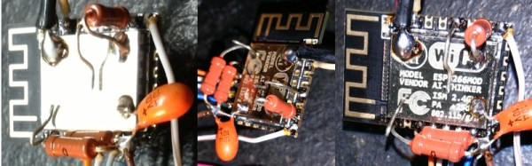
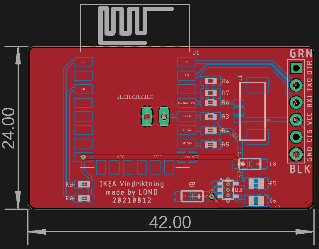
It can be a scary transition, but luckily, [Ray] has collected some notes that should prove helpful for anyone looking use modules like the ESP-12F in their own custom PCBs. From different tips on making sure the power-hungry modules get enough juice, to cost cutting measures that help reduce the ancillary parts needed in your circuit design, it’s a worthwhile read for new and experienced ESP8266 wranglers alike.

An auto-reset circuit with the CH340C

For example, [Ray] talks a bit about using the infamous GPIO10 pin. This pin is on the rear of the ESP8266 module, and on many development boards, it isn’t even connected. That’s because its internally hooked up to the ESP8266’s SPI flash chip, and using it can cause problems if you’re not careful. But as explained in the blog post, as long as you make sure the flash mode is set to “dual IO” (DIO), then GPIO10 can be used just like any other free pin.

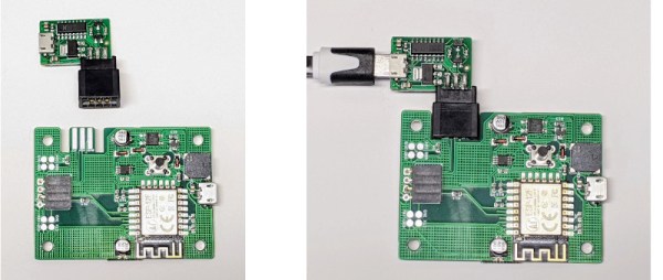
We also really liked the tip [Ray] shares at the end for making your boards more easily programmable. Sure you can leave an unpopulated header on the board, or fiddle with some pogo pin setup, but his edge connector approach is quite clever. Just slip the programmer on for the initial burn, and then after that you can update over the air.

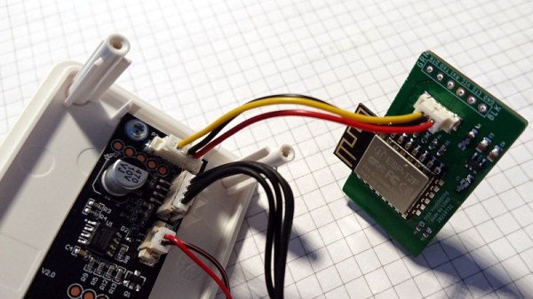
There’s no denying how easy it is to throw something together with an ESP8266 development board, but we’ve covered so many incredible projects that have made use of the bare module’s diminutive dimensions that you’ll ultimately be missing out if you don’t cut out the middle-man.

Hacked IKEA Air Quality Sensor Gets Custom PCB

Last month we brought word of the IKEA VINDRIKTNING, a $12 USD air quality sensor that could easily be upgraded to log data over the network with the addition of an ESP8266. It only took a couple of wires soldered to the original PCB, and since there was so much free space inside the enclosure, you didn’t even have to worry about fitting the parasitic microcontroller; just tape it to the inside of the case and button it back up.

Now we’ve got nothing against the quick and dirty method around these parts, but if you’re looking for a slightly more tidy VINDRIKTNING modification, then check out this custom PCB designed by [lond]. This ESP-12F board features a AP2202 voltage regulator, Molex PicoBlade connectors, and a clever design that lets it slip right into a free area inside the sensor’s case. The project description says the finished product looks like it was installed from the factory, and we’re inclined to agree.

Nothing has changed on the software side, in fact, the ESP-12F gets flashed with the same firmware [Sören Beye] wrote for the Wemos D1 Mini used in his original modification. That said [lond] designed the circuit so the MCU can be easily reprogrammed with an FTDI cable, so just because you’re leaving the development board behind doesn’t mean you can’t continue to experiment with different firmware builds.

It’s always gratifying to see this kind of community development, whether or not it was intentionally organized. [lond] saw an interesting idea, found a way to improve its execution, and released the result out into the wild for others to benefit from. It wouldn’t be much of a stretch to say that this is exactly the kind of thing Hackaday is here to promote and facilitate, so if you ever find yourself inspired to take on a project by something you saw on these pages, be sure to drop us a line.

Programmable Badge Uses E-Ink And ESP8266

You’ve probably noticed that the hacker world is somewhat enamored with overly complex electronic event badges. Somewhere along the line, we went from using a piece of laminated paper on a lanyard to custom designed gadgets that pack in enough hardware that they could have passed for PDAs not that long ago. But what if there was a way to combine this love for weighing down one’s neck with silicon jewelry and the old school “Hello my name is…” stickers?

[Squaro Engineering] might have the solution with Badgy, their multi-function e-ink name…well, badge. Compatible with the Arduino SDK, it can serve as anything from a weather display to a remote for your smart home. Oh, and we suppose in an absolute emergency it could be used to avoid having to awkwardly introduce yourself to strangers.

Powered by an ESP-12F, Badgy features a 2.9″ 296×128 E-Ink display and a five-way tactical switch for user input. The default firmware includes support for WiFiManager and OTA updates to make uploading your own binaries as easy as possible, and a number of example Sketches are provided to show you the ropes. Powered by a LIR2450 3.6 V lithium-ion rechargeable coin cell, it can run for up to 35 days in deep sleep or around 5 hours of heavy usage.

Schematics, source code, and a Bill of Materials are all available under the MIT license if you want to try your hand at building your own, and assembled badges are available on Tindie. While it might not be as impressive as a retro computer hanging around your neck, it definitely looks like an interesting platform to hack on.

ESP8266 Uses LiFi To Get On WiFi

Connecting your shiny new ESP8266 to WiFi can be as simple or as complicated as you please. Most people decide to manually add it. Some people find clever ways to make the bloody thing connect itself. [Eduardo Zola] transfers his WiFi password using the flashing light of a smartphone screen.

A simple photo-resistor and a bit of tinkering allows him to easily send credentials — or any data really — to his ESP8266, through the power of LiFi. Short for Light Fidelity, LiFi transmits data using light with on and off states representing digital values. It can use visible light, or reach into either the ultraviolet or infra-red radiation if need be. For the nitty-gritty details on the subject, check out our primer on LiFi.

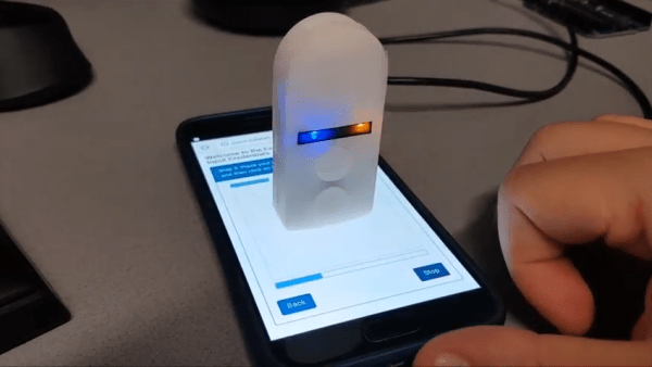
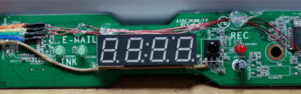
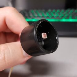
 A flashing LCD screen and a photo-resistor barely make the cut for a one-way LiFi system, but [Eduardo Zola] makes it work. The approach is to build a resitor divider and watch an input pin on the ESP for changes.

The trick is to keep ambient light out of the mix. The test sensor shown here places the LDR in a black cap, but [Eduardo] 3D-Printed a slick little enclosure for his reverse flashlight so it fits flush with the phone screen. One click and about half a minute of a flashing screen later, and the Wi-Fi credentials are transferred. This circuit could really be added onto any project, for short data transfers. With a bit more work on the sensor circuit, speed could be improved with the limiting factor being the timing on the phone screen itself.

Since the ESP8266 has its own WiFi connection, it’s likely you’ll use that for data transfer once the LiFi gets it onto the network. But any situation where you don’t have a full user input or a network connection could benefit from this. Pull out that old scrolling LED matrix project and add this as a way to push new messages to the device!
Continue reading “ESP8266 Uses LiFi To Get On WiFi”

Dumb STB Gets Smart

[Vincent Deconinck] gave a fresh lease of life to an old set top box by adding a few Euro’s worth of hardware and some software smarts. The device in question is an old VOOcorder – a Cisco set-top box provided by VOO, his cable service provider in Belgium.

The VOOcorder doesn’t have any WiFi hardware or browser / app based interfaces. It’s a simple device controlled either via an IR remote or front panel buttons. [Vincent] added an ESP8266 and hooked it up to the IR receiver on the set-top box. He also set it up as an SPI slave to the front panel VFD display controller and connected it to the debug serial interface of the VOOcorder as well. The software, on the other hand, required a lot more work consisting of code running on the ESP itself, several HTML pages and JavaScript code for the browser front end, and a few scripts running in the background.

The result was bidirectional interactivity from within a browser, allowing him to send commands and receive status information as well as providing a user-friendly search interface. Further, his browser interface was integrated with information from the service providers website letting him do scheduling and recording of programs. The stuff that interested us is how he sniffed out the IR signals, figured out the SPI protocol used by the front panel controller, and implemented SPI-slave mode for the ESP8266. [Vincent] was surprised that such a cheap device could handle three distinct web servers while parsing two message streams without a hitch.

It’s a great hack showing us how to use super cheap electronics to upgrade and modernize old hardware. Check out the two videos after the break – showing a demo of the hack in action, and a walk through of the hardware modifications.

Continue reading “Dumb STB Gets Smart”

Adding Buttons To The ESP-12 – The Cheat Way

[sorki] had an ESP-12F and wanted to play with nodeMCU, but found they were lacking buttons for reset & flash. We’ve all been there – mucking about with a project on a breadboard, trying to save the time required to solder up a button by shorting pins with wire or bending component legs to touch. This either doesn’t work or ends up bricking the microcontroller when it inevitably goes wrong. [Buger] found a tidier solution to adding buttons to the ESP-12F with the minimum of effort.

It’s the spirit of deadbug applied to buttons. One side of a piece of wire is soldered to the pin needing to be pulled down. Component leg offcuts are ideal for this. The other end of the wire is bent up and left to float over the metal shield of the ESP-12, which is connected to ground. When you want the pin to go low, press the wire into the shield, grounding it. Let it go, and the pin returns high again, assuming your pullup resistors are all in order.

It’s a quick hack that’s much more robust than trying to hold two ends of a piece of hookup wire in place. It’s also still easier than trying to find a tactile switch solder leads to, and you don’t end up having it hanging off the board either.

For deadbug construction taken to an impressive conclusion, check out this clock built out of discrete components.

[Thanks to Richard Marko for the tip!]