Surf’s Up, A Styrofoam Ball Rides The Waves To Create A Volumetric Display

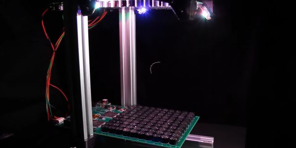
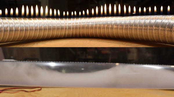
We are big fans of POV displays, particularly ones that move into 3D. To do so, they need to move even faster than their 2D cousins. [danfoisy] built a volumetric display that doesn’t move LEDs or any other digital display through space, or project light onto a moving surface. All that moves here is a bead of styrofoam and does so at up to 1 meter per second. Having low mass certainly helps when trying to hit the brakes, but we’re getting ahead of ourselves.

danfoisy vdatp 3d simulation

[danfoisy] and son built an acoustic levitator kit from [PhysicsGirl] which inspired the youngster’s science fair project on sound. See the video by [PhysicsGirl] for an explanation of levitation in a standing wave. [danfoisy] happened upon a paper in the Journal Nature about a volumetric display that expanded this one-dimensional standing wave into three dimensions. The paper described using a phased array of ultrasonic transducers, each with a 40 kHz waveform.

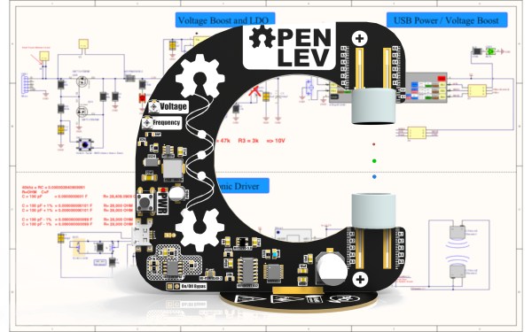
After reading the paper and determining how to recreate the experiment, [danfoisy] built a 2D simulation and then another in 3D to validate the approach. We are impressed with the level of physics and programming on display, and that the same code carried through to the build.

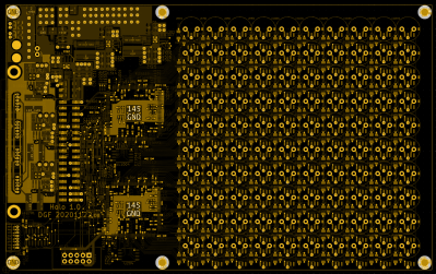
[danfoisy] didn’t stop with the simulations, designing and building control boards for each 100 x 100 10 x 10 grid of transducers. Each grid is driven by 2 Intel Cyclone FPGAs and all are fed 3D shapes by a Raspberry Pi Zero W. The volume of the display is 100 mm x 100 mm x 145mm and the positioning of the foam ball is accurate down to .01 mm though currently there is considerable distortion in the positioning.

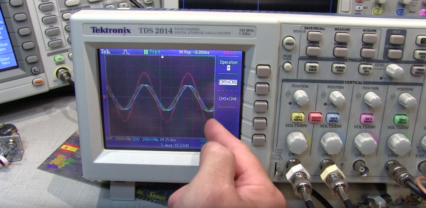
Check out the video after the break to see the process of simulating, designing, and testing the display. There are a number of tips along the way, including how to test for the polarity of the transducers and the use of a Python script to place the grids of transducers and drivers in KiCad.

danfoisy vdatp schematic  danfoisy vdatp board layout

Continue reading “Surf’s Up, A Styrofoam Ball Rides The Waves To Create A Volumetric Display”

Eye-Catching And Crumb-Suspending

Printed circuit boards used to be green or tan, and invariably hidden. Now, they can be artful, structural, and like electronic convention badges, they are the entire project. In this vein, we find Open LEV, a horseshoe-shaped desktop bauble bristling with analog circuitry supporting an acoustic levitator. [John Loefler] is a mechanical engineer manager at a college 3D printing lab in Florida, so of course, he needs to have the nerdiest stuff on his workspace. Instead of resorting to a microcontroller, he filled out a parts list with analog components. We have to assume that the rest of his time went into making his PCB show-room ready. Parts of the silkscreen layer are functional too. If you look closely at where the ultrasonic transducers (silver cylinders) connect, there are depth gauges to aid positioning. Now that’s clever.

Continue reading “Eye-Catching And Crumb-Suspending”

A Song Of Fog And Fire – Taking A Look Inside A Rubens’ Tube

The dark winter months are still a bit ahead of us, but with night returning even to the northernmost places, it might be a good time to get your next mood lighting project started. Despite the ubiquitousness of LED strips, cave-time nostalgia makes it hard to beat the coziness of an actual flame here — well, assuming it’s a controlled flame. While modern LED candles do a decent enough job to fool you from a distance, there’s one apparatus they’ll have a hard time to replicate though: the Rubens’ tube. Tired of their usual straight pipe construct, [RyanMake] added some twists and turns to the concept and created a flexible Ruben’s tube made from semi-rigid aluminum ducts.

If you’re not familiar with the Rubens’ tube, it’s a combination of science, fun, and danger to visualize standing waves with fire by attaching a loudspeaker to a pipe with equally spaced holes that’s filled with flammable gas, and light it up. As the resulting visual effect depends on the audio signal’s wavelength, and by that the length of the tube itself, [RyanMake]’s flexible duct approach adds some variety to the usual fixed-length pipe versions of it. But that’s not all he did. After seeing the flames in person, he got curious about what’s actually going on inside that tube and decided to build another one, this time using a clear plastic tube and a fog machine. While the fog escapes the tube rather unimpressively (and could hardly compete with fire anyway), it gives a nice insight of what’s going on inside those tubes. See for yourself in the videos after the break.

Of course, no experiment is truly conducted without failure, and after seeing his first tube go up in flames several times, you should probably hold on to building one as decorative item for indoors. On the other hand, if shooting fire is what you’re looking for, you might be interested in this vortex cannon. And for some more twists on a standard Rubens’ tube, check out the two-dimensional Pyro Board.

Continue reading “A Song Of Fog And Fire – Taking A Look Inside A Rubens’ Tube”

Kinetic Lamp Sheds Light On Scientific Principles

This thing right here might be the coolest desk toy since Newton’s Cradle. It’s [Stephen Co]’s latest installment in a line of mesmerizing, zodiac-themed art lamps that started with the water-dancing Aquarius.  All at once, it demonstrates standing waves, persistence of vision, and the stroboscopic effect. And the best part? You can stick your finger in it.

This intriguing lamp is designed to illustrate Pisces, that mythological pair of fish bound by string that represent Aphrodite and her son Eros’ escape from the clutches of Typhon. Here’s what is happening: two 5V DC motors, one running in reverse, are rotating a string at high speeds. The strobing LEDs turn the string into an array of optical illusions depending on the strobing rate, which is controlled with a potentiometer. A second pot sweeps through eleven preset patterns that vary the colors and visual effect. And of course, poking the string will cause interesting interruptions.

The stroboscopic effect hinges on the choice of LED. Those old standby 2812s don’t have a high enough max refresh rate, so [Stephen] sprung for APA102Cs, aka DotStars. Everything is controlled with an Arduino Nano clone. [Stephen] has an active Kickstarter campaign going for Pisces, and one of the rewards is the code and STL files. On the IO page for Pisces, [Stephen] walks us through the cost vs. consumer pricing breakdown.

We love all kinds of lamps around here, from the super-useful to the super-animated.

Start Your Path To Becoming An Antenna Guru

We’ve known a few people over the years that have some secret insight into antennas. To most of us, though, it is somewhat of a black art (which explains all the quasi-science antennas made out of improbable elements you can find on the web). There was a time when only the hams and the RF nerds cared about antennas, but these days wireless is everywhere: cell phones, WiFi, Bluetooth, and even RF remote controls all live and die based on their antennas.

You can find a lot of high-powered math discussions about antennas full of Maxwell’s equations, spherical integration and other high-power calculus, and lots of arcane diagrams. [Mark Hughes] recently posted a two-part introduction to antennas that has less math and more animated images, which is fine with us (when you are done with the first part, check out part two). He’s also included a video which you can find below.

The first part is fairly simple with a discussion of history and electromagnetics. However, it also talks about superposition, reflection, and standing wave ratio. Part two, though, goes into radiation patterns and gain. Overall, it is a great gateway to a relatively arcane art.

We’ve talked about Smith charts before, which are probably the next logical step for the apprentice antenna wizard. We also covered PCB antenna design.

Continue reading “Start Your Path To Becoming An Antenna Guru”

Visualizing RF Standing Waves

Standing waves are one of those topics that lots of people have a working knowledge of, but few seem to really grasp. A Ham radio operator will tell you all about the standing wave ratio (SWR) of his antenna, and he may even have a meter in the shack to measure it. He’ll know that a 1.1 to 1 SWR is a good thing, but 2 to 1 is not so good. Ask him to explain exactly what a standing wave is, though, and chances are good that hands will be waved. But [Allen], a Ham also known as [W2AEW], has just released an excellent video explaining standing waves by measuring signals along an open transmission line.

[Source: Wikipedia]
[Source: Wikipedia]
To really understand standing waves, you’ve got to remember two things. First, waves of any kind will tend to be at least partially reflected when they experience a change in the impedance of the transmission medium. The classic example is an open circuit or short at the end of an RF transmission line, which will perfectly reflect an incoming RF signal back to its source. Second, waves that travel in the same medium overlap each other and their peaks and troughs can be summed. If two waves peak together, they reinforce each other; if a peak and a trough line up, they cancel each other out.

Continue reading “Visualizing RF Standing Waves”