Pi Phone Lulls You To Sleep With The Digits Of Pi

As you well know, today is March 14th – aka “Pi Day”.

Celebrated in math classrooms around the country, this truly is a celebration that belongs to the geeks. Here at Hack-a-Day, we too love Pi day, though we might not outwardly celebrate it with as much gusto as expressed by some of our readers.

[Chris Poole] is one Hack-a-Day fan who knows how to make the most of this mathematical holiday. He has put together a neat SIP-based phone service that reads Pi aloud to anyone who calls. He is running Asterisk in combination with Perl to read off the numbers, and is using a free SIP DID number to accept the calls. We gave it a shot earlier today, and were greeted by a gentle synthesized voice reading off the numbers of Pi. We’re not sure how many digits it is programmed to handle, as we stopped after about 20, so give him a call and let us know how many digits you make it through.

As a parting note, no Pi Day would be complete without a few obligatory Pi-related (albeit old) web comics and pastry concoctions, so here you go!

XKCD – Pi Equals…

XKCD – e to the Pi Times i

XKCD – E to the Pi Minus Pi

Spherical Pi Pie

Battery Capacity Tester Lifts The Veil On Manufacturer Capacity Claims

battery_cap_tester

[Nick] was tasked with building a battery capacity tester by one of his teachers in order to test some aftermarket batteries that were purchased for their Vex robotics lab. The batteries were cheaper than the official version, but boasted more than twice the capacity. Fairly skeptical of the rating, he got to work designing his circuit.

He originally planned on discharging the battery through a resistor and measuring the voltage with a PIC microcontroller. After prototyping the circuit, he found that the PIC did not have enough storage space for the data he was collecting, and that there were issues with fluctuating current as the voltage decreased.

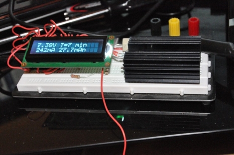
Undeterred, he built a new tester using a Teensy microcontroller and a different discharging circuit using a LM317T. This second version not only included an LCD screen to track the discharging process in real-time, but it also dumps all of the data and calculations to a spreadsheet on the computer connected to the Teensy.

The capacity tester works pretty well, according to [Nick]. He says that most batteries overestimate their capacity, and that his meter is getting readings within an acceptable variance when testing known good batteries. What about those knock-off batteries from China?  He discovered that they can hold about half the charge that they claim – it’s a good thing he decided to test them out!

While he provides the software he used for the tester, there are no schematics to be found. Check out some of the other battery capacity testers we have featured in the past for tips on building one yourself.

Guide For Working With AVR Microcontrollers

[Q] wrote in to let us know about the AVR-Guide he’s been working on. It looks like he’s finished posting about 80% of the content he planned for in his initial draft outline. We read through several of the sections and found them to be concise, yet able to present information in a way that’s easy to grasp. The screenshot above shows the most basic block of information to get started with AVR microcontrollers. We’ve covered the same information in our AVR tutorial series and think that reading through both will give you a strong understanding of the knowledge needed to work with 8-bit microcontrollers with confidence. But this resource doesn’t stop after the basics. If you’re looking to bolster your knowledge of all the features the AVR line has to offer there’s also sections explaining Digital I/O, Interrupts, Timers, Analog I/O, Communications, and Miscellaneous topics.

The site is called QEEWiki. We logged in using a Google account (this is hosted as a Google site) but didn’t see a way to edit the information. If this truly is a Wiki and you know how to edit pages please leave a comment about it after the break.

DIY Digital Pinball Console Plays Hundreds Of Games

pinball_console

Pinball machines, while likely considered pretty retro technology by most, are still a fun and engaging way to waste a little time. The problem with pinball machines is that they take up a lot of space, making the hobby of collecting them pretty prohibitive unless you have tons of spare room in your house.

[tbarklay] loves pinball machines but doesn’t have to room for an elaborate collection. Rather than purchase one machine, he opted to build his own pinball table that can be used to play any number of games. He repurposed an old PC to power his table, connecting it to a 24″ LCD panel for the main display board. A custom cabinet was built to contain the large LCD panel as well as the computer. A 19″ LCD screen was mounted on top of the cabinet to serve as the backglass display. A set of arcade buttons were also added to the console to provide realistic paddle control.

While we don’t have a video of his particular table in action, check out this video we found of  a pinball machine that uses the same setup.

Continue reading “DIY Digital Pinball Console Plays Hundreds Of Games”

Beginner Concepts: 595 Shift Register Simulator

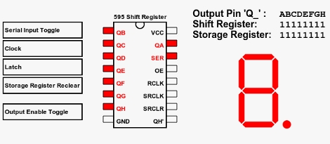
[Aaron] just finished building an online 595 shift register simulator. These inexpensive chips let you extend the number of devices that can be controlled by a single microcontroller. You see them in quite a few LED multiplexing projects, included the Ping Pong Clock that we recently built. But they can be a bit tricky to fully grasp if you’re not familiar with the hardware.

This simulator gives you a point-and-click interface for the five possible control lines on a 595 shift register. There are three pins that must be manipulated to use the device; the serial in, clock, and latch pins. The other two are for clearing the register, and enabling output and can be considered optional. You can choose to control these with a microcontroller in your own projects for more flexibility, but often they are tied to either VCC or GND (depending on the chip) when these features are unnecessary. Give this simulator a try and then take what you learned over to a solderless breadboard and see if you can write some firmware to produce the same results. If you’re still having trouble you can take a look at this 595 tutorial for further information.

Commandeering Public Video Screens: Real Or Fake?

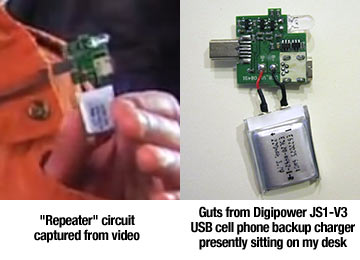
It’s time for everyone’s favorite comment thread game: Real or Fake? This week’s edition comes in from a tip that [Phil] sent about a way to take over video screens in Times Square. Watch the video after the break to see the hackers using a two-part solution to rebroadcast video from an iPhone onto a screen in the busy urban setting. The first part is a transmitter that plugs into the iPhone, the second is a signal repeater that, when held close to a video screen, overrides the clip currently being displayed with the video from the handheld. The image above shows the repeater being floated up to the big screen using a giant red balloon which you can make out in the black bar to the left of the replayed video.

Our first thought is that someone just watched Tron: Legacy and wanted to have a little Sci-Fi fun with the Internets. We can’t imagine a hardware solution that would actually make this work, but please do share your thoughts about that in the comments. We’d suspect this is more of a video hack that uses After Effects, similar to how the stopped motion candle video of the eyelid shutter glasses videos were faked. But apparently there is a follow-up video on the way that will show how the prototype was made so we could be wrong.

update: [Phil Burgess] points out that the “repeater” looks awfully familiar.

Fake for a variety of already-stated reasons (e.g. video out the headphone jack?). But the smoking gun, watching the 720P video on YouTube, is that I plainly recognize the hardware they’re using as the “repeater”: it’s simply the internals from a Digipower JS1-V3 cell phone USB boost charger (having torn apart a few myself):

Continue reading “Commandeering Public Video Screens: Real Or Fake?”

Frequency Counter For $10 Worth Of Parts

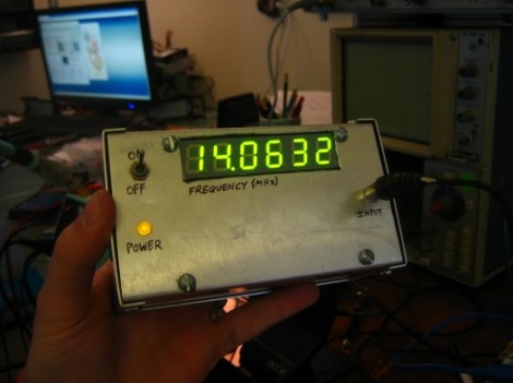
[Scott] built this frequency counter using less than $10 in parts. It’s set up to meter frequencies in megahertz which is fitting since he’s planning to use it with his radio hardware experimentation. But we would find it useful too because our cheap multimeter only reads up to around 4 MHz.

He’s using an ATmega16 that he had on hand but it has features way beyond the specs for the device. He speculates that an ATtiny2313 would easily work in its place. The microcontroller is mostly used to drive the multiplexed 7-segment display after reading the frequency values from the 74LV8154 counter chip that he is using. He doesn’t have a full schematic for the device, but there is a hand drawn diagram for using the frequency counter; the rest should be easy to piece together. Looking at that circuit we don’t think it would be too hard to make this a manual-ranging frequency counter to give you more use out of the dedicated device. Check out [Scott’s] demonstration video which is embedded below the fold.

Continue reading “Frequency Counter For $10 Worth Of Parts”