Nanoscale 3D Printing

This 3D-printed model of the Tower Bridge is only 200 micrometers long. To put that into perspective, the distance between the towers is the width of a human hair. This model is the product of research at the additive manufacturing department of the Vienna University of Technology

The models were fabricated much like normal stereolithography – a laser shines onto a vat of light-sensitive resin. The resin hardens when exposed to light, and the model is built up layer by layer. These nanoscale models were made using a process called “two-photon lithography,” something we’re not going to pretend we understand completely but here’s a nice paper that provides a good overview. Needless to say, the precision these prints exhibit are nearly ludicrous. The researchers claim a precision of ±1µm, a respectable amount of precision for very high-tech machining applications.

The researches posted a video of the fabrication of a nanoscale F1 race car filmed in real-time. Check that out after the break.


Continue reading “Nanoscale 3D Printing”

A Mannequin Head + Arduino + Webcam = Lots Of Creepy Fun!

styrofoam head robot

This mannequin head was purchased years ago on sale for less than $3. As with many things one sees while shopping, it didn’t have a purpose at the time, but seemed like it would be useful later. Add in an Arduino, some servos, and electronics parts that were acquire in a similar manner, and you have all the ingredients needed for a cool hack.

The build is well documented in the video after the break, and we especially like at 2:24 when who we suppose is the mom says “Look at this mess!” Apparently the next iteration will be a robot to clean everything up!

This iteration is quite impressive though, as it uses a webcam to track objects using a servomotor and lists the code used. For a view of it tracking stuff along with a view of the PC, fast forward to around 8:45. In addition to tracking the parts using the servo, the non-webcam eye changes color from green to yellow depending on if it’s tracking or not. It also featured a blinking necklace, which is also a plus in our eyes.

[youtube http://www.youtube.com/watch?v=TithLO3KzzU&w=470&h=315%5D

For more random head-like creepiness, be sure to check out [Boxie the Creepster]!

USB Controlled SPÖKA Night Light

usb-controlled-spoka-nightlight

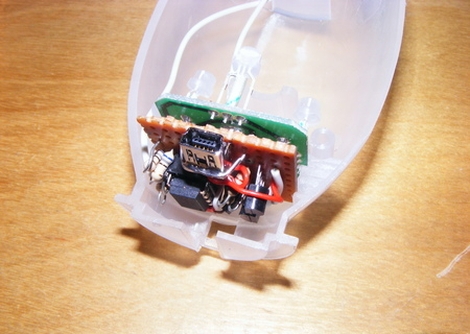
[wejp] picked up an IKEA SPÖKA night light, but he wasn’t entirely impressed with its functionality. Pressing the top of the ghost’s head causes it to cycle through a few colors, and pressing it a second time locks it into displaying the current color until its tapped again. Inspired by this SPÖKA hack which used a different version of the night light, he tore his down to see what he could do with it.

Upon stripping off the outer cover, he found that the internals were considerably different than those found in its glowing brethren, though they were perfect for what [wejp] had in mind. He removed the rechargeable battery pack as well as the controller board, which sits on a PCB separate from the LEDs. He replaced the stock micro with an ATtiny25, which he uses to give himself a bit more control over the light display.

He couldn’t quite cram all the functionality he desired into the ATtiny, but he planned on powering the light using his computer anyhow, so he installed a small USB port in the back. When connected to his PC, the SPÖKA can be controlled more precisely than when it operates alone.

Unfortunately there’s no video available of the SPÖKA light in action, but there are plenty of images available on his site.

Fine-pitch SMD Soldering With Minimal Tools

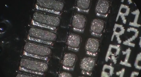
We try to stick to the 0805 parts because they’re still big enough to solder by hand. But [Scott] shows us that it doesn’t take too many special tools to reflow fine-pitch components at home. In this case he’s using 0402 resistors, a footprint that we consider functionally impossible to solder using an iron.

The two parts of the equation that he spent some money on are professionally produced PCBs and a solder stencil. The stencil is laser-cut from Kapton, which is heat-resistant so it doesn’t warp during the cutting process. An acrylic frame holds the PCB in place, and he just tapes the stencil over it and uses a chunk of acrylic as a squeegee to evenly apply the solder paste. Splurging on the PCB and stencil means you’ll achieve tolerances which lead to success.

The next issue is placing the components. [Scott] shows off some vacuum tweezers he built using an aquarium pump. Watch the video after the break to see how small those 0402 parts are when he extracts one of the resistors from the tape packaging. With the board manually populated (check everything twice!) he moves the board to a completely unaltered toaster oven for reflow. We have seen a lot of projects which add controllers to these ovens, but he really makes the case that you don’t need it. Instead, he uses a thermocoupler read by a multimeter just to let him know what’s going on with the temperature. He uses a smart phone as a timer, and switches the oven on and off to match the solder’s heat profile. Continue reading “Fine-pitch SMD Soldering With Minimal Tools”

Carabiner Helps You Hone Your Milling Skills

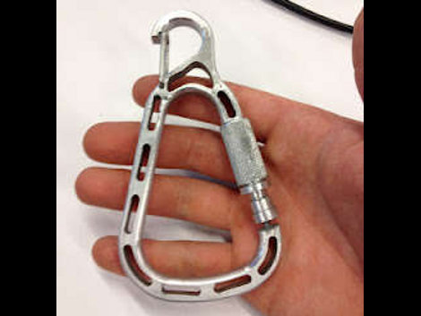
[Christian] is learning to use the metal milling tools at what we assume is his local Hackerspace. We love this about the communal spaces, they provide so many opportunities to delve into new fields. He embarked on a voyage that included visits to most of the machinery in the shop as he build his own carabiner with a magnetic gate. He’s not going to be hanging off the side of a mountain from it. But his keys or a water bottle will find a happy home thanks to the device.

It all started with some sketches to establish the shape of the overall design. From there he spent some time modelling the frame of the carabiner in CAD. He’s lucky enough to have access to a water jet which took the SolidWorks files and cut out the aluminum frame for him. That left a part with very sharp edges, so he used a wood router with a carbide bit to round them over.

The next part is adding the gate. He used an end-mill to add a mounting area on the frame. The locking ring for the gate was textured using a knurling tool, and the rest is milled with a simple cutting tool. This gate uses a magnet to center itself, with the knurled ring as the only mechanical latching mechanism. [Christian] does a good job of demonstrating the completed carabiner in the clip after the break.

Continue reading “Carabiner Helps You Hone Your Milling Skills”

Reverse Engineering Old PDA Software

[Troy Wright] acquired a lot of twenty broken Dell Axim PDAs. This type hardware was quite popular a decade ago, but looks archaic when compared to a modern cell phone. That’s why he was able to get them for a song. After a bit of work he managed to resurrect eight of the units, but was dismayed to find there’s no published method for controlling the back light from software. For some reason this is a deal-breaker for his project. But he knew it was possible because there are some apps for the device which are able to set the back light level. So he found out how to do it by reverse engineering the software.

The trick is to get a hold of the code. Since it’s not open source [Troy] used IDA, a graphical disassember and debug suite. He had some idea of what he was hunting for as the Windows CE developer documentation does mention a way to directly control the graphical hardware independently from the display driver. A few hours of pawing through assembly language, setting break points, and testing eventually led him to the solution.

Playing MP3s From An FPGA

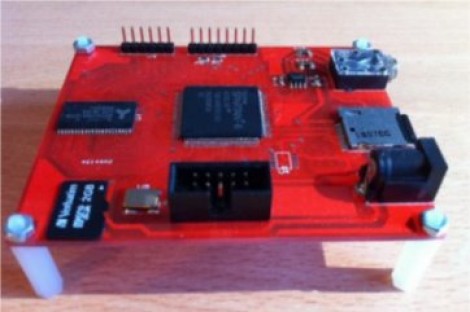
Building an audio player is a fun project. It used to be quite a task to do so, but these days the MP3 decoder chips are full-featured which means that if you know how to talk to other chips with a microcontroller you’ve got all the skills needed to pull off the project. But that must have been too easy for [Ultra-Embedded], he decided just to build an MP3 player out of an FPGA.

It’s not quite as difficult as it first sounds. He didn’t have to figure out how to decode the audio compressions. Instead he rolled the Helix MP3 decoder library into the project. It had already been optimized to run on an ARM processor, and since he’s using a RISC soft processor the translation wasn’t tough at all. He’s using a 24-bit stereo DAC chip to bridge the gap between the audio jack and the FPGA output. Clocking that chip with the FPGA isn’t ideal and causes 44.1 kHz audio to run 3% too slow. He says it’s not noticeable, which we believe. But if you try to play along with a song the pitch shift might end up driving you crazy.

If you’d prefer to just stick to the microcontroller based players this one’s small and inexpensive.