Weather Clock Puts OLPC To Work

weather-clcok

A clock to tell the weather? [Andrew] has created a device to do that and more. Inspired by [Sean’s] weather clock, [Andrew’s]clock displays the current weather conditions, temperature, moon phase, and of course the time. The whole project started years ago with a broken keyboard. [Andrew] wanted to try to use the keyboard controller PCB as a bidirectional computer interface. Data to the computer would go in via the key matrix. Output data would be read via the status LEDs. Cheap simple microcontroller boards like the Arduino sidelined the project for a few years, but he never completely left it behind.

With an unused OLPC XO-1 in hand, [Andrew] pulled out his old keyboard controller and started hacking. His first task was getting meaningful data out of the keyboard LEDs. He coded up his own keyboard led control library in python. On the hardware side an op amp took on the roll of a comparator to ensure proper logic levels were present. [Andrew] then hooked two LEDs up as clock and data lines to standard 74 series shift registers (most likely 74HC/HCT595). He found that his data was completely garbled due to bounce. A second shift register buffering the clock cleaned things up. [Andrew] was left with a stable 40 bits per second serial link to his shift registers. With all this done, the next step was the clock itself. [Andrew] bought a RUSCH Wall clock from IKEA, and converted the clockwork to a gear reduction for a DC motor he pulled from an old answering machine. He could now move the hands at will, but had no way to determine their position. IR break beam sensors from old printers came to the rescue.

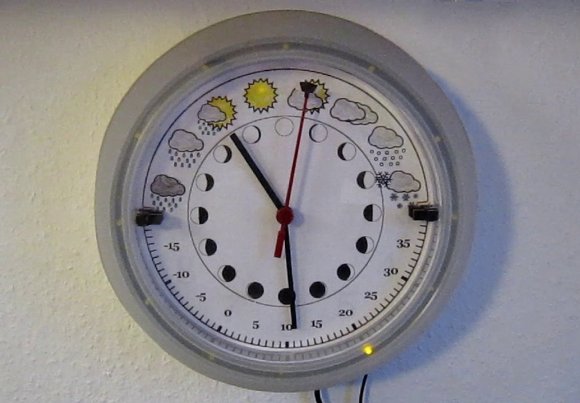
After connecting the motor drive, [Andrew] still had a number of outputs available. A few LEDs were in his parts box, so into the project they went. 12 LEDs around the outside of the clock to display the current time. 3 LEDs hide behind the weather icons as status indicators. [Andrew’s] python software really ties this together. His OLPC grabs data from the internet and displays it on the clock. A web interface allows the user to perform manual updates on the clock and to set alarms. The alarms even incorporate speech output via eSpeak. We love the reuse and recycling of parts in this hack. The end result is a clock any hacker would be proud to display on their wall.

Continue reading “Weather Clock Puts OLPC To Work”

Companion Cube Christmas Lights Improved With Neopixels

cubes

[Crenn] obtained a string of official companion cube lights from Valve, but being in Australia couldn’t put them to their non-judgemental glory without the use of a step down transformer. They sat on the workbench for a few months until an idea was hatched: replace the bulbs with an Adafruit Neopixel strip, making these wonderful inanimate friends a string of individually addressable RGB LEDs.

The process of converting these cubes required stuffing a very small 9.4mm PCB inside. This PCB was designed in KiCAD thanks to a few classes at the Melbourne hackerspace. The board files were sent off, PCBs received, soldered up, and stuffed into the cubes.

Control is via a Duemilanove with a single IO pin using the Neopixel library. All the code, board files, and schematics are available on the gits. Future improvements might include a 3D printed cable relief and a way to securely mount the PCBs to the inside of the cubes.

Video available below.

Continue reading “Companion Cube Christmas Lights Improved With Neopixels”

OpenKnit, The Open Source Knitting Machine

For all the hubbub about 3D printers leading a way into a new era of manufacturing, a third industrial revolution, and the beginnings of Star Trek replicators, we really haven’t seen many open source advances in the production of textiles and clothing. You know, the stuff that started the industrial revolution. [Gerard Rubio] is bucking that trend with OpenKnit, an open-source knitting machine that’s able to knit anything from a hat to a sweater using open source hardware and software.

We’ve seen a few builds involving knitting machines, but with few exceptions they’re modifications of extremely vintage Brother machines hacked for automation. OpenKnit is built from the ground up from aluminum extrusion, 3D printed parts, a single servo and stepper motor, and a ton of knitting needles.

The software is based on Knitic, an Arduino-based brain for the old Brother machines. This, combined with an automatic shuttle, allows OpenKnit to knit the sweater seen in the pic above in about an hour.

Since OpenKnit is inspired by the RepRap project, all the files, software, and assembly instructions will be up on Github shortly. there’s also a video available below, and a Flickr gallery right here.

Continue reading “OpenKnit, The Open Source Knitting Machine”

Replacing A Tire Valve Stem Without Special Tools!

Your car’s tire is losing air from the valve stem — what do you do? Well you could take it to the mechanic and pay upwards of $30 to replace it… or you could try this MacGyver style approach!

Not wanting to take his car to the shop, [David] tried several ways of knocking the tire off its bead. Hitting it with a sledge hammer… Jumping on it… throwing it against the ground… In the end, he realized leverage would be his friend! He’s constructed a tool out of a few pieces of wood — simply place it on the tire near the valve stem, and then drive up the wood with your car. The weight of the car easily compresses the tire leaving you just enough room to pull the tire valve stem out, and put a new one in.

It’s pretty much the same method shops use, they just have a machine to do it for them — because of this, so we don’t think this would hurt your tire. As always though, we’d love to hear what you guys think in the comments! Stick around for the video to see [David’s] process.

Continue reading “Replacing A Tire Valve Stem Without Special Tools!”

FT232RL: Real Or Fake?

Above are two FTDI FT232RL chips, an extremely common chip used to add a USB serial port to projects, builds, and products. The one on the left is a genuine part, while the chip on the right was purchased from a shady supplier and won’t work with the current FTDI drivers. Can you tell the difference?

[Zeptobars], the folks behind those great die shots of various ICs took a look at both versions of the FT232 and the differences are staggering. Compared to the real chip, the fake chip has two types of SRAM etched in the silicon – evidence this chip was pieced together from different layouts.

The conclusion [Zeptobars] reached indicated the fake chip is really just a microcontroller made protocol compatable with the addition of a mask ROM. If you’re wondering if the FTDI chips in your part drawers are genuine, the real chips have laser engraved markings, while the clone markings are usually printed.

Vector Display Output On An Oscilliscope

V3zirb1

What can we say, we’re a sucker for projects featuring our logo. That being said, this one is seriously awesome. [CNLohr] has figured out how to create a vector display output on an oscilloscope… from a VGA port.

He was inspired by a game called Trace Vector, which is done in the same style as some of the old classics like Asteroids. This got [Charles] thinking, and he decided to see what it would take to make his own vector capable display. An oscilloscope is perfect for this, as it already works by controlling the position of the beam (like a vector), as opposed to standard LCDs and CRTs that use rasterizing (horizontal scanning). This means to get the oscilloscope to display a graphic, all you need to do is to vary the voltages going into the X and Y channels — well, at a high speed!

But where are you going to find such a high speed digital to analog converter? Oh yeah, your computer’s VGA port! For a few dollars [Charles] threw together a VGA adapter with a few resistors using just the red and blue outputs (source code). A bit of programming later, and he’s created his own vector display!

Stick around to see our lovely skull and cross-wrenches rotate on his oscilloscope! Oh, and for a more in depth explanation and more impressive vector video demonstration.

Continue reading “Vector Display Output On An Oscilliscope”

3D Printering: Making A Thing With Solidworks, Part I

printering1

Brian has graciously allowed me to hop on the 3D Printering bandwagon to write a brief intro to the wonderful world of Solidworks. We’ll be making the same ‘thing’ as done in the previous ‘Making a Thing’ tutorials:

engineeringdrawingblack1

Admittedly, most Hackaday readers probably don’t have Solidworks as it is a very expensive program. The main reason we are posting this tutorial is so that you can understand the work flow and compare it to some of the free/open packages out there.

Continue reading “3D Printering: Making A Thing With Solidworks, Part I”