An Engineer’s Guide To Cooking The Perfect Turkey

It’s almost that special time of year again where we all get together and use our families as guinea pigs for new cooking techniques and untested recipes! Some of us are seasoned pros at preparing the big bird of tradition, while others are still experimenting year after year with hopes of nailing the optimal method by chance. [Travis Mikjaniec] approaches this culinary conundrum from an engineer (of aerodynamicist)’s perspective, with the goal of scientifically discerning through simulation the best method to prepare a Thanksgiving turkey; no long term trial and error required.

thermoTURKEY2

As the basics of cooking dictate, the rate at which the meat of a turkey will cook is determined by where the hot air is flowing and gathering inside the oven. Areas of the bird subjected to consistent fresh heat will cook faster and are more likely to dry out over time, so it’s important that the hot air is equally dispersed for an evenly cooked, juicy turkey. To figure out the trajectory of the air and the point where it begins to cool down, [Travis] modeled the naked bird in CAD, complete with the hallow cavity within. He then recreated the baking conditions to use in FloEFD, in this case a standard convection oven with a fan located in back. To compare cooking techniques against one another, he ran a series of streamline simulations with combinations of different cooking variables, like how high the bird was lifted off the baking sheet and whether or not the inner cavity had the added thermal mass of stuffing or not. These chaotic diagrams of simulated air flow helped visualize which conditions were conducive for even heating.

If you’re interested in knowing the verdict of [Travis’] trials with virtual turkeys, he offers thorough documentation on his investigative blog post. His insight might help improve your cooking game plan for Thanksgiving or teach you something you didn’t know about the aerodynamics of a fifteen pound headless bird… which is something you can talk about while sitting around the table.

Scope Noob: Probing Alternating Current

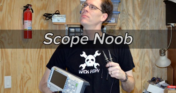
I finally did it. After years of wanting one (and pushing off projects because I didn’t have one) I finally bought an oscilloscope. Over the years I read and watched a ton of content about how to use a scope, you’d think I would know what I’m doing. Turns out that, like anything, hands-on time with an oscilloscope quickly highlighted the gaping holes in my knowledge. And so we begin this recurring column called Scope Noob. Each installment will focus on a different oscilloscope-related topic. This week it’s measuring a test signal and probing Alternating Current.

Measuring a Signal

test-signal

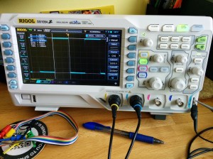
Hey, measuring signals is what oscilloscopes are all about, right? My very first measurement was, of course, the calibration signal built into the scope. As [Chris Meyer] at Sector67 hackerspace here in Madison put it, you want to make sure you can probe a known signal before venturing into the unknown.

In this case I’m using channel 2. Everything on this scope is color-coded, so the CH2 probe has blue rings on it, the probe jack has a blue channel label, and the trace drawn on the screen is seen in blue. I’m off to a fantastic start!

This scope, a Rigol 1054z, comes with an “auto” button which will detect the signal and adjust the divisions so that the waveform is centered on the display. To me this feels like a shortcut so I made sure to do all of this manually. I started with the “trigger” which is a voltage threshold at which the signal will be displayed on the screen. The menu button brings up options that will let you choose which channel to use as trigger. From there it was just a matter of adjusting the horizontal and vertical resolution and position before using the “cursor” function to measure the wave’s voltage and time.

I played around with the scope a bit more, measuring some PWM signals from a microcontroller. But you want to branch out. Because I don’t have a proper signal generator, the next logical thing to measure is alternating current in my home’s electrical system. I suppose you could call it a built-in sine wave source.

Probing Alternating Current

acac-wall-wart

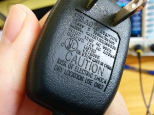
I sometimes take criticism for never throwing things away. Seven years ago we had a cat water fountain whose motor seized. It was powered by a 12V AC to AC converter seen here. Yep, I kept it and was somehow able to find it again for this project.

Of course at the time I thought I would build a clock that measures mains frequency to keep accurate time. This would have done the trick had I followed through. But for now I’m using it to protect me (and my fancy new scope) from accidental shock. I’ll still get the sine wave I’m looking for but with a source that is only 12V at 200 milliamps.

Don’t measure mains directly unless you have a good reason to do so.

Continuing on my adventure I plugged in the wall wart and connected the probe to one of the two wires coming out of it. But wait, what do I do with the probe’s reference clip? I know enough about home electrical to know that one prong of the plug is hot, the other is neutral. The clip itself is basically connected directly to mains ground. Bringing the two together sounds like a really bad idea.

This turns out to be a special case for oscilloscopes, and one that prompted me to think about writing this column. Had this been a 3-prong wall wart, connecting the probe’s reference clip to one of the wires would have been a very bad thing. Many 3-prong wall warts reference the mains earth ground on one of the outputs. If that were the case you could simply leave the clip unconnected as the chassis ground of your scope is already connected to mains ground via its own 3-prong power cord and the reference clip is a dead short to that. If you did need to probe AC using the reference clip you need an isolation transformer for your scope. There are bigger implications when probing a board powered from mains which [Dave Jones] does an excellent job of explaining. Make sure you check out his aptly named video: How NOT to blow up your oscilloscope.

As I understand it, and I hope you’ll weigh in with a comment below, since the wall wart I’m using has a transformer and no ground plug I’m fine using the ground clip of the probe in this case. Even though I’m clipping it to an AC line, the transformer prevents any kind of short between hot/neutral mains and earth ground (via the probe’s ground clip). What I don’t understand is why it’s okay to connect the transformed side of the 12V AC to mains ground?

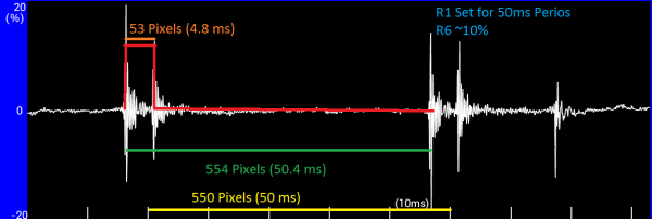
At any rate, the screenshots above show my progress through this measurement. I first connected the probe without the ground clip and got the sad-looking trace seen on the left. After conferring with both [Adam Fabio] and [Bil Herd] (who had differing opinions on whether or not I should “float the scope”) I connected the ground clip and was greeted with a beautifully formed sine wave. I’m calling this a success and putting a notch in the old bench to remember it by.

What’s Next?

bridge-recctifier-teaserI don’t want to get too crazy with the first installment of Scope Noob so I’ll be ending here for now. I need your guidance for future installments. What interesting quirks of an oscilloscope should a noob like me explore? What are your own questions about scope use? Leave those below and we’ll try to add them to the lineup in the coming weeks.
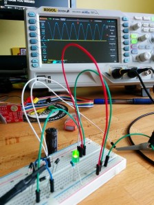
Homework

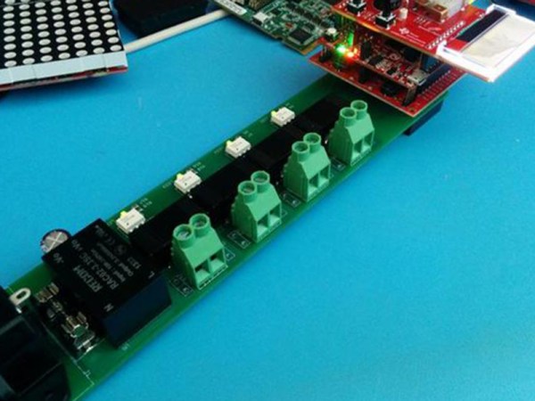
For next week I’m working my way through the adventure of rectifying this 12V AC signal into a smoothed DC source. Here you see a teaser of those experiments. I’ve built a full-wave rectifier using just four diodes (1N4001) and will plunk in a hugely-over-spec’d electrolytic capacitor to do the smoothing. If you want to follow along on the adventure you should dig around your parts drawers for these components and give it a try yourself this week. We’ll compare notes in the next post!

Easy And Effective Way To Measure PWM… Without A Scope!

Sometimes when a project is coming together, you need to cobble a tool together to get it completed. Whether it’s something very involved, like building a 3D printer to fabricate custom parts, or something relatively simple, like wiring a lightbulb and a battery together to create a simple continuity checker, we’ve all had to come up with something on the fly. Despite having access to an oscilloscope, [Brian] aka [schoolie] has come up with his own method for measuring PWM period and duty cycle without a scope, just in case there’s ever a PWM emergency!

The system he has come up with is so simple it’s borderline genius. The PWM signal in question is fed through a piezo speaker in parallel with a resistor. The output from the speaker is then sent to an FFT (fast fourier transform) app for Android devices, which produces a picture of a waveform. [schoolie] then opens the picture in MS Paint and uses the coordinates of the cursor and a little arithmetic to compute the period and the duty cycle.

For not using a scope, this method is pretty accurate, and only uses two discrete circuit components (the resistor and the speaker). If you’re ever in a pinch with PWM, this is sure to help, and be a whole lot cheaper than finding an oscilloscope!

telepresence

Telepresence Robot Demo Unit Breaks Free Of Its Confinement

What happens when you put a telepresence robot online for the world to try out for free? Hilarity of course. Double Robotics is a company that builds telepresence robots. The particular robot in question is kind of like a miniature Segway with a tablet computer on top. The idea is you can control it with your own tablet from a remote location. This robot drives around with your face on the screen, allowing you to almost be somewhere when you can’t (or don’t want to) be there in person.

Double Robotics decided to make one of these units accessible to the Internet as a public demonstration. Of course, they couldn’t have one of these things just roaming about their facility unrestrained. They ended up keeping it locked in an office. This gives users the ability to drive it around a little bit and get a feel for the robot. Of course it didn’t take long for users to start to wonder how they could break free from their confinement.

One day, a worker left the office door cracked open ever so slightly. A user noticed this and after enough patience and determination, managed to use the robot to get the door opened. It appears as though the office was closed at the time, so no one was around to witness the event. A joy ride ensued and the robot hid its tracks by locking itself back in the room and docking to the charging station.

While this isn’t a hack in the typical sense, this is a perfect example of the hacker mindset. You are given some new technology and explore it to the extent at which you are supposed too. After that, many people would just toss it aside and not give it a second thought. Those with the hacker mindset are different, though. Our next thought is usually, “What else can I do with it?” This video demonstrates that in a fun and humorous way. Hopefully the company learns its lesson and puts a leash on that thing. Continue reading “Telepresence Robot Demo Unit Breaks Free Of Its Confinement”

Turkey Sous Vide

It’s time once again for Americans to gorge themselves on hormone-laced meats covered in several sauces and gravies, all of which inexplicably contain corn syrup. It’s also Thanksgiving this Thursday, so there’s that, too. If you have a turkey defrosting somewhere, you’ve probably gone over all your cooking options – the oven, a giant propane-heated pot of peanut oil, and yes, even sous vide. [Trey] over at TI came up with a great sous vide controller using a few LaunchPad Booster packs, and surprisingly, he can even cook a turkey.

The basic idea of sous vide is to vacuum pack your protein, put it in a closely-controlled water bath, and cook it so the inside is always the same temperature as the outside. It’s delicious, and it takes a long time. We can automate that, though.

[Trey] is using a USB LaunchPad and a thermocouple BoosterPack to monitor the temperature of a water bath. A custom SSR board is wired right into the heater, and a CC3100 provides a network connection to monitor the bird. While the network may seem a bit superfluous, it’s actually a great idea; sous vide takes hours, and you really don’t dote on your warm tub of water. Being able to receive SMS alerts from a sous vide controller is actually a great idea.

With everything wired up, [Trey] tried out his recipe for deep-fried turkey porchetta. From the pictures, it looks great and according to [Trey] it was the juiciest turkey he’s ever had.

AlienFX

Simple Terminal Hack Is Fit For Hollywood

We’ve all seen the cheesy hacker scenes in movies and on TV. Three dimensional file system browsers, computer chip cityscapes, and other ridiculous visualizations to make the dull act of sitting at a keyboard look pretty on the silver screen. While real hackers know those things are often silly and impractical, sometimes we do go out of our way to pretty things up a bit.

Hollywood might be able to learn a thing or two from this latest hack. [Yuri] modified his Linux terminal to change the color of the back lights on his laptop’s keyboard. It’s the kind of thing that actually would look good in a modern hacker movie, and [Yuri] is living proof that it’s something that a real-life hacker would actually use!

[Yuri] has been running Simple Terminal. The Simple Terminal project aims to build a replacement for the default xterm program that removes all of the unnecessary features and simplifies the source code. It also aims to make your terminal experience prettier. Part of making things prettier means that you can choose the font color for your terminals, and of course each terminal window can have its own color if you so choose.

[Yuri] happens to own an Alienware laptop. This laptop comes with RGB LEDs behind the keyboard, allowing you to light them up just about any color you could ever want. [Yuri] thought it would be cool if his keyboard color matched the font color of his terminal windows. Thanks to AlienFX, he was able to write a simple patch for Simple Terminal that does exactly this. Now whenever he selects a terminal window, the keyboard automatically switches colors to match the text in that window. Be sure to check out the video below. Continue reading “Simple Terminal Hack Is Fit For Hollywood”

Open Sourcing Satellite Telemetry

Launched in 1978, the International Sun/Earth Explorer 3 was sent on a mission to explore the Earth’s interaction with the sun. Several years later, the spacecraft changed its name to the International Cometary Explorer, sent off to explore orbiting ice balls, and return to Earth earlier this year. Talking to that spacecraft was a huge undertaking, with crowdfunding campaigns, excursions to Arecibo, and mountains of work from a team spanning the globe. Commanding the thrusters onboard the satellite didn’t work – there was no pressure in the tanks – but still the ICE mission continues, and one of the lead radio gurus on the team has put up the telemetry parser/display crafted for the reboot project up on Github.

The guy behind the backend for the ICE/ISEE reboot project should be well-known to Hackaday readers. He’s the guy who came up with a Software Defined Radio source block for a cheap USB TV tuner, waking everyone up to the SDR game. He’s also played air traffic controller by sitting out near an airport with a laptop, and has given talks at Black Hat and DEFCON.

The ICE/ISEE-3 telemetry parser/display allows anyone to listen to the recorded telemetry frames from the satellite, check out what was actually going on, and learn how to communicate with a device without a computer that’s rapidly approaching from millions of miles away. He’s even put some telemetry recordings up on the Internet to practice.

Although the ICE/ISEE-3 reboot project will have to wait another decade or two until the probe makes its way back to our neck of the woods, [Balint] is taking it in stride an organizing a few Software Defined Radio meetups in the San Fransisco area. He just had the first meetup (Video below) where talks ranging from creating a stereo FM transmitter in GNU radio, a visual introduction to DSP for SDR and SETI signals from the Allen Telescope Array were discussed. There will be another meetup in a few weeks at Noisbridge, with some very cool subjects on the roster.

Continue reading “Open Sourcing Satellite Telemetry”