Temperature Data Logger

Temperature Data Logger Logs Temperature Over Time

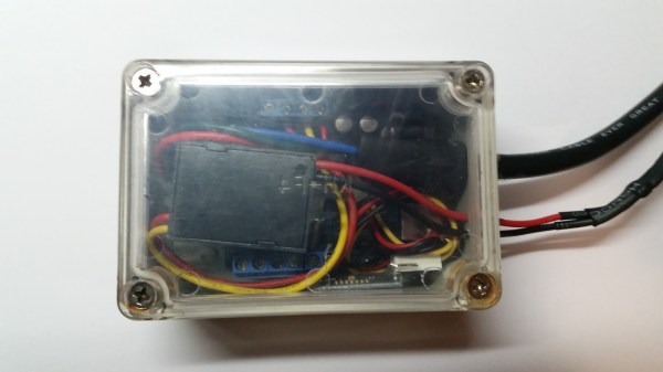
Temperature Data Logger[Husham] not only likes his electronics projects but clearly enjoys documenting them as well. He’s written a nice Instructable on a Temperature Data Logger that he has built and thankfully makes his code available for others to use. The end product is cleanly designed and made for weather-proof outdoor applications.

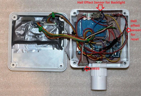
As you may expect, the brains behind this operation is an Arduino. It is coupled with a Real Time Clock to maintain accurate timing as well as an SD Card Module which is used to store the data collected. In this case, the temperature is read by a LM35 temperature sensor and that value, along with the time, is recorded to a .csv file on the SD card in one minute intervals.

There is also an LCD screen that displays the date, time and current temperature. To save battery life the LCD backlight is normally off. It can be turned on using a magnet that interacts with a hall effect sensor on the top of the case. This worked so well that [Husham] installed a second hall effect sensor on the side of the case that resets the Arduino. Speaking of the case, it is a weather proof PVC electrical box with a conduit adapter installed on the bottom side. A battery pack made up of two used laptop cells housed in a piece of conduit supplies 7.2 volts to the Arduino and other components. Unfortunately, there’s no word on how long the battery pack lasts. Once the data is logged, the SD card can be removed and the .csv file opened in spreadsheet software to make a graph showing temperature change over time.

Bluetooth Fuel Monitor

Bluetooth Enabled Fuel Consumption Monitor

[Malebuffy] bought himself a used boat last year. Fuel isn’t exactly cheap where he lives, so he wanted a way to monitor his fuel consumption. He originally looked into purchasing a Flowscan off the shelf, but they were just too expensive. In the interest of saving money, [Malebuffy] decided to build his own version of the product instead.

To begin, [Malebuffy] knew he would need a way to display the fuel data once it was collected. His boat’s console didn’t have much room though, and cutting holes into his recently purchased boat didn’t sound like the best idea. He decided he could just use his smart phone to display the data instead. With that in mind, [Malebuffy] decided to use Bluetooth to transmit the data from the fuel sensors to his smart phone.

The system uses an older Arduino for the brain. The Arduino gets the fuel consumption readings from a Microstream OF05ZAT fuel flow sensor. The Arduino processes the data and then transmits it to a smart phone via a Bluetooth module. The whole circuit is powered from the boat battery using a DC adapter. The electronics are protected inside of a waterproof case.

[Malebuffy’s] custom Android apps are available for download from his website. He’s also made the Arduino code available in case any one wants to copy his design.

Hacklet 29 – Altoids Mint Tin Projects

Altoids – they’ve been around since King George III was on the throne. These curiously strong mints have had a storied history, a copy of which is included in every tin. They taste pretty good, but most hackers and makers are more interested in the pocket-sized tin than the mints themselves. It may have been the ham radio operators who first used Altoids tins to hold their sensitive transmitter and receiver circuits. The metal case makes a perfect electromagnetic field shield. It wasn’t long before the tins found their way into thousands of projects. This week’s Hacklet features some of the best projects with Altoids (and other mint) tins on Hackaday.io!
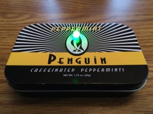
meeting-timerWe start with [Chad Lawson] and the Networking Group Timing Light. [Chad] has a networking meeting where each member has two minutes to introduce themselves. As is the case with most meetings, people tend to be a bit long-winded, running well beyond their allotted two minutes. The timing light contains an RGB LED which changes from green to yellow to red as a speaker’s time ticks away. The timer is reset by simply tilting the mint tin. [Chad] is hoping that the timer will serve as a gentle reminder to keep everyone on track time-wise.
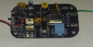
 

radio2Next up is [Rjpope42] and his AM/FM Transmitter Pair. [Rjpope42] loves vintage tube radios, and wants to send his own signals to his amber glowing projects. Wiring an external audio input to a tube radio is pretty easy, but nothing beats a simple AM transmitter for convenience. Small FM transmitters are commonly available to add an MP3 player input to cars without an AUX audio in, but their AM counterparts have become rare. [Rjpope42] has built AM and FM transmitters, each of which will fit in a Mint Tin case. The AM transmitter can run on 9V or 12V, and even includes a USB power output for charging an MP3 player or phone!
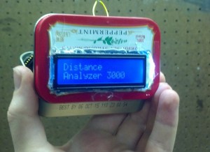
da31k[John Hamann] entered Distance Analyzer 3000 in the Trinket EDC contest. While he didn’t win, it was still a great project, especially since this is [John’s] first serious Arduino project. The idea is to use a rotary encoder with a wheel to measure distances. Think of it like a mini version of a surveyor’s walking wheel. The Pro Trinket counts the pulses from the rotary encoder, then converts this to a distance in feet. We’d love to see [John] continue on the project. An ultrasonic distance sensor would be a great addition for multi-sensor distance reads!
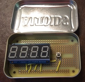
 

ttotpFinally, we have [colonwq] with TTTOTP, a pro trinket Time based One Time Password (TOTP) generator. [colonwq] used the trinket to implement the well-known time based one time password algorithm. To implement a project like this, you need a stable time source. The ATmega328 isn’t very good at this, so [colonwq] used a Dallas DS1307 clock chip to keep track of things. The actual code is displayed on a 4 digit 7 segment display. When the button is pressed, the first half of the code is displayed. Once the button is released, the second half of the code is displayed for several seconds.


Need more mint? Check out our curiously awesome mint tin project list!

Hackaday.io Update and MeArm Giveaway

Hackaday.io has a few new features, including @username and #projectID. If you mention someone’s username with an @ in front of it, that user will get a notification in their stack. The same goes with mentioning a project ID with a # up front. To celebrate this, we’re giving away a pair of  special edition MeArms. All you have to do is leave a comment using the features on this project log. Huge thanks to [Jasmine] for setting all this up, and to [Ben] for letting us hijack his project for the week!

That’s it for this Hacklet, As always, see you next week. Same hack time, same hack channel, bringing you the best of Hackaday.io!

Circuit Printers: Voltera And Voxel8

There are two printers being shown off at the 2015 Consumer Electronics shows which really spark our interest. They are the Voltera and the Voxel8. Each is taking on the challenge of printing circuits. They use similar techniques but approach the problem in very different ways.

Voxel8

The Voxel8 marries the idea of a 3D printer with a silver conductive ink dispenser. You start by modeling your entire design, hardware and electronics, all in one. The printer will then begin the 3D print, pausing when necessary for you to add electronics and mechanicals. With the parts — and their pins — in place it lays out the conductive ink to connect the components and then continues with the 3D printing to finish the object.

Voltera

The Voltera is a PCB printer that uses silver conductive ink. It prints the ink onto a substrate. Pads made of the ink are used to solder the components in place after the printing is finished. The trick added to this design is the ability to print two layers, both on the same side of the board. There is a second ink material which is an insulator. It is laid over the first conductive layer before the second is printed, allowing traces to cross over each other.

Congratulations to the Voltera team who won $50k from the 2015 Hardware Battlefield at CES.

Our Thoughts

We didn’t see enough to shake our skepticism about the viability of silver conductive ink to take the place of copper on prototype boards. But if anyone is going to make the case that it is plausible these two offerings will.

One interesting thing about the Voxel8 is the ability to specify point-to-point wiring as a “part”. If you do so, the machine will pause while you solder the wires in place before it encapsulates them with the rest of the print. Of course if you’re going to do this manually it shouldn’t really matter which printer you use for it.

What do think about the future of conductive ink for prototyping? Lets us know in the comments.

CES: Meetups, Augmented Reality, And Robots

Hackaday started off Thursday of the Consumer Electronics Show with an impromptu breakfast meetup. This turns out to be a wonderful thing as it lets you ease into a 16 hour day of standing, walking, talking, and getting lost trying to find your way from conference hall to conference hall. We had a great turnout and many brought their hacks and demos to show off. A big thanks to the Sambalatte staff who are awesome people and top tier baristas.

CastAR

DSC_0354

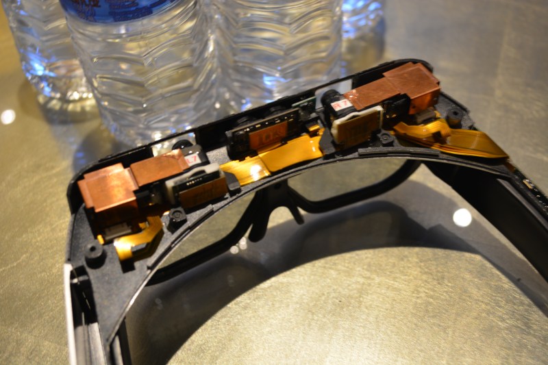
Before leaving for CES I was talking to [Ben Krasnow] about what we should try to see and he suggested looking for private showings that are given in the suites of the hotels at the conference. Turns out our friends at Technical Illusions are doing just that. [Jeri] and [Rick] were showing off CastAR in a suite during the week and were nice enough to make room in their booked schedule for a private Demo.

What you see above are the guts of the version they are currently shipping as part of their Kickstarter fulfillment. I also got a look at a rev2 prototype and will write a follow-up post with more information on the whole experience when I have more time.

Eureka, Startups!

There is a loop of aisles in the Sands that has startup booths and most of the interesting things I saw on Wednesday and Thursday are there. Here we have a jamming gripper robot arm. It’s designed for things like moving oddly shaped goods on a manufacturing line. Empire Robotics hit a homerun with their demo for the booth, a take on beer-bong: robot versus human. The scoreboard showed the robot winning an order of magnitude more than the humans.

[Todd] was at was at the Tinkerines booth showing off 3D printers aimed to augmented the STEM curriculum. We couldn’t help but notice his TIE fighter right and inquired about it. He modeled the design himself, send it off to be cast in silver, and inlaid the stone when the ring came back from the casting service. Sweet!

LVBots

[Sarah Petkus] clued me in and gave me a ride to the Pololu CES open house. The night coincided with the LVBots meetup which they support by providing space for the meetings. There were lots of cool robots being shown off. What you see here was just the pre-meeting warmup of line-followers and sumo robots. I shot some video of the show-and-tell which we’ll post once we’ve had a chance to edit the content.

Closing out CES

wpid-wp-1420824368323.jpegToday is the last day of the conference. I stopped by the Voltera PCB printer booth yesterday but they were nowhere to be found. Turns out they were being handed a $50k check by TechCrunch for winning the Battleground. I suppose we’ll give them a pass for not being at the table during that!
I’ll be headed over this afternoon to catch up with them. I’m also hoping to get a look at the Voxel8 printer. If you have any other “can’t-miss” suggestions let me know in the comments and I’ll try to add them to my CES dance card.

Dual Complementary Optoisolator Logic

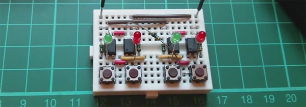
You’ve seen CMOS logic, you’ve seen diode-resistor logic, you’ve seen logic based on relays, and some of you who can actually read have heard about rod logic. [Julian] has just invented optoisolator logic. He has proposed two reasons why this hasn’t been done before: either [Julian] is exceedingly clever, or optoisolator logic is a very stupid idea. It might just be the former.

Inside each optoisolator is a LED and a phototransistor. There’s no electrical connection between the two devices, which is exactly what you need in something that’s called an isolator. [Julian] was playing around with some optoisolators one day to create a weird push-pull circuit; the emitter of one phototransistor was connected to the collector of another. Tying the other ends of the phototransistor to +5V and Gnd meant he could switch between VCC and VDD, with every other part of the circuit isolated. This idea whirled around his mind for a few months until he got the idea of connecting even more LEDs to the inputs of the optoisolators. He could then connect the inputs of the isolators to +5V and Gnd because of the voltage drop of four LEDs.

A few more wheels turned in [Julian]’s head, and he decided to connect a switch between the two optoisolators. Connecting the ‘input’ of the circuit to ground made the LED connected to +5V light up. Connecting the input of the circuit to +5 made the LED connected to ground light up. And deeper down the rabbit hole goes [Julian].

With a few more buttons and LEDs, [Julian] created something that is either an AND, NAND, OR NOR, depending on your point of view. He already has an inverter and a few dozen more optoisolators coming from China.

It is theoretically possible to build something that could be called a computer with this, but that would do the unique properties of this circuit a disservice. In addition to a basic “1” and “0” logic state, these gates can also be configured for a tri-state input and output. This is huge; there are only two universal gates when you’re only dealing with 1s and 0s. There are about 20 universal logic gates if you can deal with a two.

It’s not a ternary computer yet (although we have seen those), but it is very cool and most probably not stupid.

Video below.

Continue reading “Dual Complementary Optoisolator Logic”

The Original Seven (Eight?) Segment Display

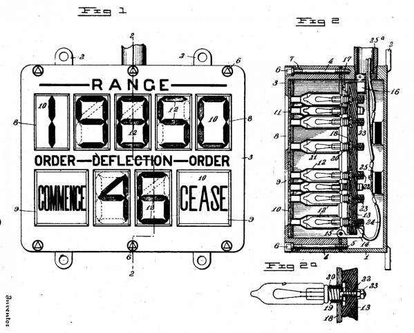
The seven-segment LED display is ubiquitous. But how old do you think the fundamental idea behind it is? You nixie tube fans will be thinking of the vacuum-tube era, but a reader sent us this patent filed in 1908 where [Frank W. Wood] builds a numeric display with plain-vanilla light bulbs, slots cut in wood, and lots of wires.

The OCR on the patent is poorly done — you’re going to want to download the PDF and read it locally. But as it states in the patent, “Referring again to Fig. 1, the novel arrangement of the lamp compartments will be readily understood.”

Technically it’s not a seven-segment display at all. [F.W. Wood] designed these really nice-looking “4”s with the diagonal heads, and so he needed eight segments per digit. But the basic idea shines through, if you pardon the pun.

The other figures demonstrate the machine that’s used to send the signals to light up the lights. It’s a rotating drum with the right contacts on the bottom side to make connections and turn on the right lights at the other end. Low tech, but it’s what was available at the time.

We’re stoked that we’re not responsible for wiring this thing up, and we’re a bit awed by how old the spirit behind one of our most ubiquitous technologies is.

Thanks to [mario59] for the nostalgic tip!