Just about the hardest thing you’ll ever do with a microcontroller is video. The timing must be precise, and even low-resolution video requires relatively large amounts of memory, something microcontrollers don’t generally have a lot of. HDMI? That’s getting into microcontroller wizard territory.
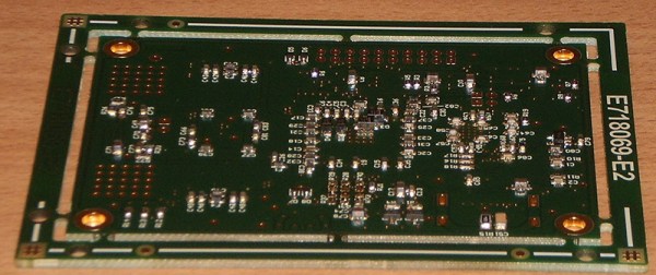
Despite these limitations, [monnoliv] is working on a GPU for microcontrollers. It outputs 1280×720 over HDMI, has a 24 bit palette, and 2D hardware acceleration.
It’s a very interesting project; usually, if you want graphics and a display in a project, you’re looking at a Linux system, and all the binary blobs and closed source drivers that come with that. [monnoliv]’s HOMER video card doesn’t need Linux, and it doesn’t need a very high-powered microcontroller. It’s just a simple SPI device with a bunch of memory and an FPGA that turns the most minimal microcontroller into a machine that can output full HD graphics.
This isn’t the only open source graphics card for microcontrollers in the Hackaday Prize; just a few days ago, we saw VGAtonic, another SPI-controlled video card for microcontrollers, this time outputting VGA instead of HDMI. Both are excellent projects, and if either makes it into production, they’ll both be cheap: under $100 for both of them. Just the thing if you want to play around with high-resolution video without resorting to Linux.
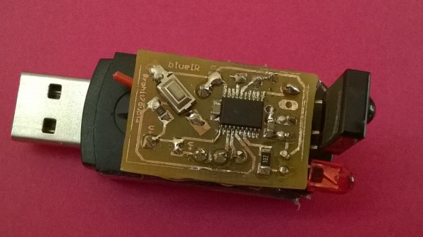
Quite often, the raison d’être for building a project is to learn and hone one’s skills. In which case it doesn’t matter if the end use seems a bit frivolous. [indiantinker] built BlueIR, a device to control Bluetooth A2DP devices using an archaic IR Remote using a BT-Aux Adapter.
Sounds convoluted? Let’s try again. He uses an old IR remote to send data to a MSP430-series microcontroller, which is connected over serial to a USB Bluetooth Receiver Adapter, which in turn is connected to a set of wired speakers. The Bluetooth adapter is paired with his phone. The IR remote allows him to control the audio player commands on his phone from a far greater distance compared to the bluetooth adapter.
He begins by breaking open the BT adapter to find that the markings on the chip have been erased. What he did find instead, were two pads promisingly marked as TX and RX, but he still did not know the baud rate or the command set. Digging around the Internet, he figured out that the chip used was the OVC3860 Bluetooth 2.0 + EDR Stereo Audio Processor and found its list of AT Commands. After some tests using a serial console he figured out that it worked at 115600 baud. Soon enough, he had it hooked up to the MSP430 Launchpad and was able to communicate. Next up, he built a small PCB, using the toner transfer method. The board consists of the MSP430G2553 micro controller, IR receiver, LED, some decoupling capacitors and a few pull up resistors. He leached power from the 3.3V regulator on the host BT adapter. The assembled PCB is piggy backed on top of the BT adapter for the time being, and a 3d printed housing is on his to-do list. His code is available at the BlueIR Github repo and the video below shows it in action.
For the last two weeks, we’ve been asking everyone over on hackaday.io to participate in the current round of community voting. We were asking everyone to choose the projects that were Most Likely To Be Widely Used. We just turned off voting for this round, and it’s time for round two: Which project is most likely to save the planet?
Before we get to that, I need to pick a random person on hackaday.io, figure out if they have voted, and if so, send off a $1000 gift card to the Hackaday store. Vidya time:
No one won a $1000 gift card for the Hackaday store this week. In lieu of that, we’re arming the t-shirt cannon and aiming it at three random people who did vote. They are, in order of appearance, [Nick], [dbcarp], and [Eugene].
If you’re wondering about the results of this current round of voting and which projects the Hackaday community think are most likely to be widely used, hold tight. There are a lot of votes, and all that needs to be tabulated and computed and presented in a friendly graphical format. Also, it’s Friday afternoon. The winners of the first round of voting will be announced on Monday.
Round Two…. Most Likely To Save The Planet
It’s time for a new round of voting! This time, the theme is, Most Likely To Save The Planet. Voting is easy, just go over to the community voting page. You will be presented with two projects entered in the Hackaday Prize. One of these projects will invariably be more likely to save the planet. It is your task to decide which one. Vote for the project that is more likely to save the planet, and you’re in the running for t-shirts or Hackaday store gift cards in the drawing next week.
That’s all you have to do to vote in the Hackaday Prize community voting. Here’s a link to go do that. We’ll do the same thing next Friday afternoon – choose a random person on Hackaday.io, and if they have voted, they get a $1000 gift card for the Hackaday store. The only losing move is not to play, so go vote.
It’s an interesting proposition; there is no company serving the maker community – and those of us who refuse to call ourselves part of the maker community – more hated than MakerBot. They’ve patented ideas uploaded to Thingiverse. They’ve turned their back on the open hardware community they grew out of, They’re undercutting their own resellers, and by all accounts, they don’t know how to make a working extruder. MakerBot was the company that would show the world Open Hardware could be successful, but turned into a company that seemed to reject Open Hardware and Open Source more than any other.
Nevertheless, questions were collected, The MakerBot CEO was interviewed by Lady Ada, and a summary compiled. You can check that interview, originally posted on the Adafruit blog, below.
Over the last decade or so, USB has somehow changed. It’s not just for connecting printers, keyboards, mice, and webcams any more. It’s not even just for stuff you would have plugged into a serial port. It’s a power outlet. If you want to charge your phone, plug it into a power outlet that can deliver up to 2.5 Watts. Unintended consequences, I guess. If you ever find yourself in 1995 again, go over to Intel and tell them to bump up the current limit.
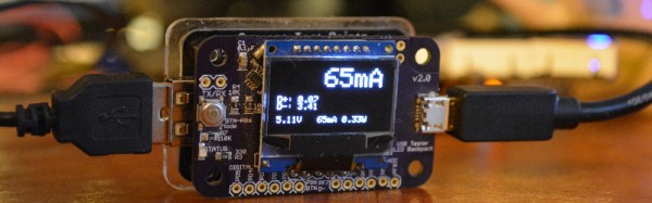
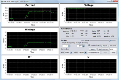
Being a power outlet, having a device to measure current, voltage, power, and all the other intricacies of the what’s going on inside a USB cable would be neat. The USB Tester from Fried Circuits is that device.
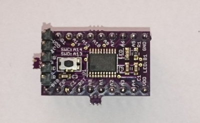
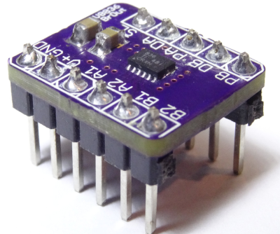
The Fried Circuits USB tester isn’t so much a single device, but a small set of tools that allow you to probe everything going on inside a USB cable. In its simplest form, it’s just a board with a USB A connector at one end, a USB micro connector at the other, and breakouts for measuring current, voltage, the differential data signals, and that weird ID pin that’s useful if you’re working with USB chargers or OTG devices.
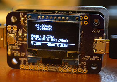
This breakout board also has two rows of five pins broken out. That’s for the USB Tester Backpack, which is really the heart of this device. This backpack features a microcontroller and a 128×64 resolution OLED display for current, voltage, and power monitoring, reading the voltage on the data lines, and graphing everything on the display. Everything you would ever want to know about a USB port – except for the actual bits being shoved through, of course – is right there on the display. Press the button on the side a few times, and whatever info you need will be presented in tall, very readable numbers.
The Entire Reason For Buying One
If you’re only going to use this to look at voltages, amps, and current flowing through a USB cable, you’re throwing your money away with this USB Tester. If simple, at-a-glance monitoring is what you need, you can hop on Amazon and get a USB current/voltage meter for $15. Even Adafruit has one for $7.50. If you only need to read the volts and amps for a USB device, your money is better spent elsewhere.
The Fried Circuits Java app.
The Fried Circuits USB tester does something none of these other USB meters can do. It can log all the data to a computer over USB.
In my initial review of the USB Tester for the Hackaday Store, the only ‘official’ option for recording data from the Tester to a computer was a Java app. The developer of the USB Tester, [Will], chose Java because of the ‘write once, run anywhere’ Sun and Oracle have been shoving down our throats for the last 20 years. In theory, Java was an excellent choice for a datalogging solution for the USB Tester.
In practice, however, it just didn’t work. By [Will]’s own admission, it was the first thing he’s ever done in Java, and I think he set some of the options in NetBeans wrong. I could not get the data logging app to run on my Windows 8 box, or my OS X box, or my Linux boxxen. The only way I could run this app was by digging out an old XP box. Apparently, [Will]’s copy of NetBeans was configured for Java 5 or something.
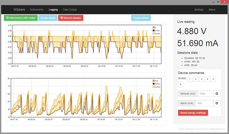
[Will] knew about this problem, and last month he officially teamed up with [Edouard Lafargue] of wizkers.io. This is a platform for scientific instruments that runs in a Chrome App. The choice of running instrumentation in a Chrome app may seem odd, but this is apparently the new hotness; you can program an Arduino in a Chrome app, and there’s a lot of interesting stuff happening in this space.
The Wizkers.io app can do everything you would expect from a datalogging app. It will tell you the volts, amps, watts, mWh, and mAh of the device currently under test. There are pretty graphs, and everything can be downloaded to a computer for further analysis.
It might seem like cheating to review this device with a 3rd party app, but by [Will]’s own admission, there were problems with the Java-based logger, and the Chrome app works perfectly. There’s also the delicious irony that a Chrome app is more portable than one written in Java. I appreciate that.
Of course the USB Tester also outputs this data over a serial connection (in JSON format, too!). If you just want to connect this to a computer, solder up some wires to the TX and RX lines.
Conclusion
If you want a device that just tells you how many mA a USB device is sucking up, you don’t need this. You can buy something for less than $10 that will tell you that. If you’re developing some USB hardware, you’ll eventually want to characterize how much power your device is drawing and when it’s drawing that much power. This will require a data logging tool, and apart from cutting up a few USB cables and wiring it into an expensive power supply, you can’t do better than the Fried Circuits USB tester.
Starting a design with a new part can be hard. What power supply voltage(s) does it need? Are there any support component requirements? What is the footprint? What about the I/O voltage levels? Breakout boards are designed to answer all those questions for you. Breakouts help when you’re designing with a new part – be it a microcontroller, a sensor, a motor driver, or anything else. They also are a huge help when you’re trying to knock out a quick hack, and just need to get something working quick. Fast to integrate, often breadboard friendly, breakouts just make things easier! This week’s Hacklet is about some of the best breakout board projects on Hackaday.io!
We start with [Christoph] and STM32F030F4P6 breakout board. Inspired by the Teensy 3.0, [Christoph] set out to build a simple, easy to use, and small breakout board for an ARM processor. The STM32F030F4P6 is a great starting point. At only 20 pins, it’s one of the smallest ARM based chips around. He added the basic things needed to bring this chip up: decoupling caps, a reset button, headers for ST’s software debugger, and of course an LED for a blinky hello world program. The resulting board is physically tiny, but this lilliputian ARM board packs Coretex M0 powered punch!
Next up is [al1] and DRV8836 Breakout. Sooner or later, everyone wants to drive a motor in one of their projects. It’s a rite of passage, just like blinking an LED. Motors pull a lot of current though, so external transistors or driver chips are almost always necessary. TI’s DRV8836 chip packs two full H-bridges into one package. That’s enough to drive two DC motors or one stepper. Handling 1.5 amps of current per driver in a tiny package means that thermal coupling is important. The DRV8836 has a large thermal pad which has to be soldered to keep the magic smoke in. [al1] dropped the chip, along with the correct thermal footprint and decoupling capacitors onto a simple breakout. The result is easy to use motor drivers for the masses.
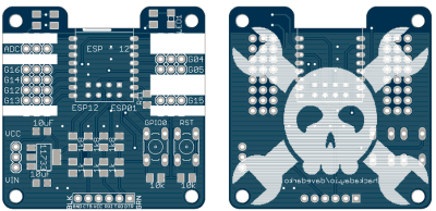
Hackaday.io power user [davedarko] took cues from his favorite designs to create Ignore this ESP8266 board. In [Dave’s] own words, “I stole from every one. The huzza from Adafruit, [Matt’s] breakout board, [Al1s] board, NodeMCUs DevKit.” Hey [Dave] there’s no stealing in open source hardware! There is only design reuse with attribution, which is exactly what you’re doing. [Dave’s] breakout can use both popular ESP8266 footprints: the ESP-01 and ESP-12. He’s added power, reset/programming buttons, and the all important serial header to talk to the module. Going serial allows dave to keep costs down by not including an expensive serial to USB chip in the BOM. Most of us have FTDI cables (or clones) bouncing hanging around anyway. We definitely like the logo on this one!
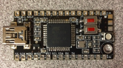
Finally we have [The Big One] with uBBB 32u4. uBBB 32u4 is a bigger brother of µbbb, a Hackaday.io project [Warren] and [The Big One] worked on. µbbb uses an Atmel ATmega32u2 processor. [The Big One] has expanded the faimly to include an ATmega32u4. If you’re wondering, uBBB stands for “Micro Bare Bones Board” At 1.65″ x 0.8″, this is a micro board. It still manages to include everything you need to get the processor up and running fast. Crystal, buttons, decoupling caps, and LEDs – everything is here. A mini USB connector makes communicating with the ATmega a snap!
If you want to see more breakout boards, check out our new breakout board list! If I’ve forgotten to add you to the list, just drop me a message on Hackaday.io. That’s it for this week’s Hacklet, As always, see you next week. Same hack time, same hack channel, bringing you the best of Hackaday.io!
Week 19 of the Caption CERN Contest is now in the record books, though we’re sure we’ll be getting “safety update” emails from HR about the incident for the next several weeks. Thanks to everyone who threw caution to the wind and submitted a caption! This definitely is some sort of medical or emergency room at CERN. We’re still not quite clear as to why they need a full-sized skeleton though. We have to wonder how many lab pranks that poor former-human has been part of.
The Funnies:
“The second test subject survived a bit better than the first, and if you’re wondering, the first test subject is standing in the corner”- [jakewisher125]
“It soon became apparent that it had been a mistake to entrust site security to sharks with lasers.” -[Robb Smith]
“What do you mean blink once if it hurts? Are you serious?” – [Rollyn01]
Anyone who’s worked on a major project, be it professional, personal, or for a contest like The Hackaday Prize, knows about marathon sessions. Those times when you put in your all and just push the project ahead until you drop. This scientist has definitely given his all and then some! He’s catching a few winks right under the blackboard where he presumably has been working. This image has no caption, though it’s attached to an album entitled Linac control room. None of the pictures seem to show much of a control room though. It seems that back in 1966, CERN’s photographer was a bit more interested in the sleeping scientists than the science itself!
What do you think is happening in this image? Can you make anything interesting out from the diagrams on the blackboard? Give it a shot! This week’s prize is a Stickvice from The Hackaday Store.
Add your humorous caption as a comment to this project log. Make sure you’re commenting on the contest log, not on the contest itself. As always, if you actually have information about the image or the people in it, let CERN know on the original image discussion page.