Color By Number 3D Printing Style

Remember paint-by-number kits? Your canvas has outlines with numbered regions that you paint with correspondingly numbered paints. When you are done, you’ve recreated the Mona Lisa. [KurtH3] uses a similar technique to coax multicolor prints from his 3D printer.

The technique isn’t general purpose, but it still is an interesting way to add some color to your usually monochrome prints. The idea is simple: You find a paint-by-number layout (apparently, you can find them with a Google search). Use your favorite method to get the outline into a CAD program. [KurtH3] doesn’t really get into the details about this, but some CAD programs will directly import images. Others will require you to trace in Inkscape (or a similar program) and convert to a vector format like DXF that the 3D CAD program can import.

Here’s the trick: instead of extruding the 2D image as one piece, you extrude the numeric regions to slightly different heights. Say you wanted to print a red, white, and blue flag to a thickness of about 5mm and you use 0.2mm layers. You could extrude the white part to 5mm, for example. Then the red parts could be extruded to 5.2mm (one layer higher) and the blue parts to 5.4mm. You could extend the idea to do multiple layers, although that will increase the surface roughness.

[KurtH3] pauses the print at the end of the layers to change filament, but we would probably edit the sliced G-Code to put pauses in the right places (for example, Repetier Host lets you put @pause in your file). You could also use software to split the G-Code as we’ve previously covered.  The resulting print, using our example, would be white from the bottom up but would have thin red and blue layers over the top in the right places. The few hundred microns difference from the white surface to the other colors means you won’t get a perfectly smooth surface, but a few hundred microns shouldn’t be too noticeable.

Continue reading “Color By Number 3D Printing Style”

Microcontroller Adjustment Of A DC To DC Converter

[Hugatry] wanted to replace the adjustment pot on an LM2596 buck converter with a microprocessor-controlled voltage. The regulator IC uses a divider to generate a 1.25V reference from the output. The pot is part of a divider circuit that sets the output voltage. For example, if the divider is 10:1, the controller will keep the output at 1.25V and, therefore, the output voltage will be 12.5V.

[Hugatry’s] strategy was to use a filtered PWM signal from a microcontroller to offset the 1.25V signal. By adding a small voltage to the control point, the output voltage would not need to rise as high as before to maintain the 1.25V reference. For example, adding 0.25V to the reference input would only require 1V, which corresponds to a 10V output.

The video has a nice view of a scope showing the relationship between the PWM duty cycle and the output voltage. Although he didn’t mention it, it struck us that since PWM is proportional to the supply voltage, the voltage on the microcontroller and PWM output stage probably needs to be fixed. That implies you couldn’t use the buck converter to directly power the microcontroller itself. Then again, what kind of microcontroller needs to adjust its own power supply?

Continue reading “Microcontroller Adjustment Of A DC To DC Converter”

Hackaday Prize Entry: The 70s Called. They Want This Calculator

For those of us who grew up during TI’s calculator revolution, the concept of reverse polish notation (RPN) might be foreign. For other more worldly calculator users, however, the HP calculator was ubiquitous. Hewlett-Packard peaked (at least as far as calculators are concerned) decades ago and the market has remained dominated by TI since. Lucky for those few holdouts there is now a new microcode emulator of these classic calculators.

Called the NP25 (for Nonpariel Physical), the calculator fully emulates the HP-21, HP-25C and HP-33C. It’s a standalone microcode emulator, which means that these calculators work exactly as well as the original HP calculators of the 70s did. The new calculators, however, are powered by a low power MSP430G2553 processor and presumably uses many, many fewer batteries than the original did. It has an LED display to cut power costs as well, and was built with the goal of being buildable by the average electronics hobbyist.

Even if you didn’t grow up in the 70s with one of these in your desk drawer, it’d still be a great project and would help even the most avid TI user appreciate the fact that you don’t have to use RPN to input data into calculators anymore. Not that there’s anything wrong with that. This isn’t the only calculator we’ve featured here, either, so be sure to check out another free and open calculator for other calculator-based ideas.

Continue reading “Hackaday Prize Entry: The 70s Called. They Want This Calculator”

clock

Ferrofluid Clock Is A Work Of Art

It is not usually too difficult to separate functionality from art. Consider a clock. It’s a machine that has a clear and distinct function. It provides information. Nothing could be more different from a clock on a wall than a piece of artwork.  A painting, for instance has no clear function and provides no information. It’s just…art. It’s nice to look at. If we were to ask you to build a functioning, information providing clock that is also a piece of artwork, you would surely have your hands full. Where would you even start? If your name was [Zelf Koelma], you’d grab a bottle of ferrofluid and build us a beautiful, almost mesmerizing clock.

clock_01There’s little to no information on the details of how the clock works other than the use of ferrofluid. But it’s not hard to guess that it uses dozens of electromagnets and an Arduino. You can even pick one up for a cool $8,300 if you’re lucky enough to get a spot on the list, as he’s only making 24 of them.

Want to make one of your own? Pick up some ferrofluid and keep us updated. We’d love to hear from you in the comments on how you’d implement a build like this one. We had a fun time hearing your ideas when we covered the clock made of clocks.

Continue reading “Ferrofluid Clock Is A Work Of Art”

Reflow Solder Your Micro SD To Ensure It Doesnt Go Anywhere

SD cards are great inexpensive storage for your embedded project. Using SPI,  they only take a few wires to hook up, and every micro-controller has a FAT file system interface to drop in your project. Problem with SD cards are the connectors.

Usually connectors cost more than the brains of your project,  and the friction fit, spring loaded contacts are not ideal for temperature swings, humidity and high vibration applications. Wouldn’t it be nice if you could just solder the thing down, especially if you know you are never going to remove it?

[Timothée] decided to try and succeeded in reflow soldering a Micro SD card direct to a breakout board. While starting as a what if experiment, the PCB was laid out in Ki-Cad and sent off to a fab. Once returned the Micro SD was fluxed, tinned and fluxed again, then reflowed using an IR setup.

The end result is a handy breakout board where you never have to worry about someone swiping the card to jam in their camera, and is ready for any breadboard project.

Adventures With Vacuum Deposition Power Supplies

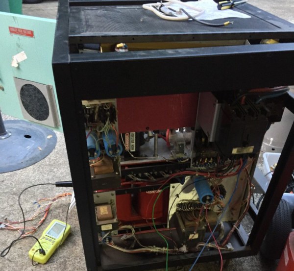
[macona] called this a “fail of the week”, but of course failure is just another part of the hacker adventure. Fail and fail often! He’s been slowly assembling a vacuum deposition system. These systems let you deposit thin films on a substrate. Vacuum deposition systems have all sorts of exciting applications, not only are they used in semiconductor manufacturing, but as [Ben Krasnow] has shown can create conductive transparent coatings. They’re even sometimes used for silvering mirrors.

A common feature of these systems is that they require high voltage, we’re not talking a few hundred volts or even a few thousand volts. But 10 to 20 kilovolts. You need such a high voltage in order to accelerate electrons and ions, which are used to eject atoms from a source and deposit them as a thin film on a substrate.

It was this HV supply [macona] was working on, cobbling the system together from parts found on eBay. Unfortunately he could only reach 9kv unloaded, which we’d expect to drop considerably under load. So [macona] has now found a different solution. But this teardown and write up still makes great reading.

We’re left to pondering on what projects the spare parts could be useful for: “I might be able to series the secondaries and get 30kv at 500ma! That would make one hell of a bug zapper! Actually these transformers scare the hell out of me….” me too Jerry! Me too!

Embed With Elliot: The Volatile Keyword

Last time on Embed with Elliot we covered the static keyword, which you can use while declaring a variable or function to increase the duration of the variable without enlarging the scope as you would with a global variable. This piqued the curiosity of a couple of our readers, and we thought we’d run over another (sometimes misunderstood) variable declaration option, namely the volatile keyword.

On its face, volatile is very simple. You use it to tell the compiler that the declared variable can change without notice, and this changes the way that the compiler optimizes with respect to this variable. In big-computer programming, you almost never end up using volatile in C. But in the embedded world, we end up using volatile in one trivial and two very important circumstances, so it’s worth taking a look.

Continue reading “Embed With Elliot: The Volatile Keyword”