Clever Chemistry Leads To Much Faster 3D Printing

Resin printing, it can be messy but you get really great resolution thanks to the optical nature of curing the sticky goo with light from a projector. Soon it will have a few more notches in its belt to lord over its deposition cousins: speed and lack of layers. A breakthrough in resin printing makes it much faster than ever before and pretty much eliminates layering from the printed structure.

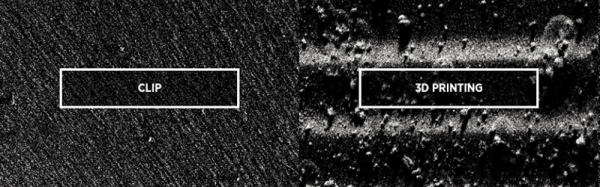
The concept uses an oxygen-permeable layer at the bottom of the resin pool. This inhibits curing, and apparently is the source of the breakthrough. The resin is cured right on the border of this layer and allows for what is described as a continuous growth process rather than a layer-based approach. One of the benefits described is no need for resin to flow in as the part is extracted but we’re skeptical on that claim (the resin still needs to flow from somewhere). Still, for us the need to work with resin which is expensive, possibly messy, and has an expiry (at least when compared to plastic filament) has kept deposition as a contender. The speed increase and claims of strength benefits over layer-based techniques just might be that killer feature.

The technology is coming from a company called Carbon3D. They are branding it CLIP, or Continuous Liquid Interface Production. After the break you can see a video illustration of the concept (which is a bit too simple for our tastes) as well as a TED talk which the company’s CEO, [Joseph Desimone] gave this month. Of course there is also the obligatory time-lapse print demo.

So what do you think: game changer or not, and why do you feel that way? Let us know in the comments.

Continue reading “Clever Chemistry Leads To Much Faster 3D Printing”

Measuring Heart Rate With A Piezo

Look around for heart rate sensors that interface easily to microcontrollers, and you’ll come up with a few projects that use LEDs and other microcontrollers to do the dirty work of filtering out pulses in a wash of light.

[Thomas] was working on a project that detects if water is flowing through a pipe with a few piezoelectric sensors. Out of curiosity, he taped the sensor to his finger, and to everyone’s surprise, the values his microcontroller were spitting out were an extremely noise-free version of his heart rate.

The piezo in question is a standard, off the shelf module, and adding this to a microcontroller is as easy as putting the piezo on an analog pin. From there, it’s just averaging measurements and extracting a heartbeat from the data.

It’s a much simpler solution to measuring a heart rate, and since two people haven’t heard of this technique, it’s likely a lot more people haven’t heard of this technique either. If you’re looking for an entry to The Hackaday Prize, this would be a great jumping off point for anything in either the fitness or medical domains.

Machining A Yo-Yo With Speed Holes

A while ago, [Gord] received a notice from his daughter’s school looking for silent auction donations for a fundraiser. It’s pretty much a bake sale, only [Gord] gets to build something. He has a pretty nice machine shop, and eventually settled on building a pair of beautiful vacillating vertical pendulums. They’re yo-yos, in case you were wondering what that meant.

Each half is cut out of a 2.5″, with both sides of each half faced off and tapped. From there, eighteen speed holes shave off 22 grams of weight. The sides of the yo-yo are shaved down to a thickness of half an inch, a 14° bevel is put on each face, the edges are chamfered at 30°, and everything is polished up.

Sending a bare metal yo-yo to a raffle is apparently a little uncouth, so [Gord] anodized each half of the yo-yos in a bath of sulfuric acid, then applied dye to the surface. With everything assembled, a fancy glass and metal case was constructed and a certificate of authenticity printed out. It’s a brilliant final touch to a great project, we just wish we knew how the yo-yo performed.

Thanks [Chris] for sending this in.

SXSW Create: Sparkfun Gives Kids Awesome Badges To Hack

By far the most desirable booth for the crowds at SXSW Create was the Sparkfun quadrant. We call it a quadrant because they had a huge footprint approaching 1/4 the tented area, but it was well used. They brought a number of staff down to Austin in order to give away a legit electronic badge project they call BadgerHack.

sxsw-sparkfun-badgerhack-kit-thumbWe love badge hacking. LOVE IT! But South-by isn’t purely a hardware conference so the badges aren’t made of PCBs (for shame). Add to that, free entry to Create scores you a wristband but no badge.

This is the answer to that, a badge giveaway and build-off aimed at kids but cool enough to make me feel only slightly awful for accepting one when I pretty much knew they were going to run out before the final day was done.

The USB stick PCB is, as you guessed it, an Arduino compatible loaded up with an FTDI chip and an ATmega328p which they call the BadgerStick. Accompanying this is a multiplexed 8×7 LED matrix board. Solder the three pin headers and the battery holder leads, connect to the plastic badge using the supplied double-stick tape, and you have a badge that scrolls a message in LEDs.

DSC_0508What an awesome giveaway. I really like it that they didn’t cut corners here. First off, the kids will value the badge much more because they had to actually assemble it rather than just being handed a finished widget. Secondly, there is the USB to serial chip and USB footprint that means they can reprogram it without any extra equipment. And an LED matrix… come on that’s just a gateway drug to learning Wiring. Bravo Sparkfun and Atmel for going this route with your marketing bucks.

The badge activity rounded out with some hardware interfacing. There’s a 3-pin socket that attendees could plug into 4 different stations around the booth. Once done they received a coupon code for Sparkfun that scrolls whenever the badge is booted up. For some at-home fun, the writeup (linked at the top) for the BadgerHack firmware is quite good. It offers advice on changing what is displayed on the badge and outlines how to build a game of Breakout with just a bit of added hardware.

Under The Hood – What Does This Board Do?

As interesting as it is to look at the insides of de-capped chips, it is equally interesting to sometimes look at old circuit boards and try to figure out the various sections, their functions, and to look at some of the design practices used. At a local electronics flea market, [daqq] recently chanced upon quite a large PCB that seemed to have come from some HP system, and picked it up for about 6 – the value of the abundant oscillators, crystals, connectors and other miscellaneous components that could be recovered seemed much more than what he paid for the board.

The board in question turned out to be from a HP 9000 Superdome system – part of the PA-8xxx based server series which packs quite a punch. This particular one was the 500MHz system UGUY5-500 board. At this point, most of [daqq]’s analysis is based on what he can visually decipher looking at the chip numbers and associated parts. He’s taken a stab at guessing the function of the board itself, and of the various parts on it. He’s put up high resolution scanned images of the board, for any of our readers who would like to offer an insight in to this board or the system that it was part of. Apparently, he has quite a few more exotic server PCB’s lined up for sleuthing, if you folks enjoy this.

DIY Oscilloscope With A Scanning Laser

If you’ve ever used an old-school analog oscilloscope (an experience everyone should have!) you probably noticed that the trace is simply drawn by a beam that scans across the CRT at a constant rate, creating a straight line when there’s no signal. The input signal simply affects the y-component of the beam, deflecting it into the shape of your waveform. [Steve] wrote in to let us know about his home-built “oscilloscope” that works a lot like a simple analog oscilloscope, albeit with a laser instead of  a CRT.

[Steve]’s scope is built out of a hodgepodge of parts including Lego, an Erector set, LittleBits, and a Kano Computer (based on a Raspberry Pi). The Pi generates a PWM signal that controls the speed of a LittleBits motor. The motor is hooked up to a spinning mirror that sweeps the laser across some graph paper, creating a straight laser line.

After he got his sweep working, [Steve] took a small speaker and mounted a mirror to its cone. Next he mounted the speaker so the laser’s beam hits the mirror on the speaker, the spinning sweep mirror, and finally the graph paper display. The scope’s input signal (in this case, audio from a phone) is fed into the speaker which deflects the laser beam up and down as it is swept across the paper, forming a nice oscilloscope-like trace.

While [Steve]’s scope might not be incredibly usable in most cases, it’s still a great proof of concept and a good way to learn how old oscilloscopes work. Check out the video after the break to see the laser scope in action.

Continue reading “DIY Oscilloscope With A Scanning Laser”

New Part Day: SPI RAM And A Video Controller

Generating video signals with a microcontroller or old CPU is hard if you haven’t noticed. If you’re driving even a simple NTSC or PAL display at one bit per pixel, you’re looking at a minimum of around 64kB of RAM being used as a frame buffer. Most microcontrollers don’t have this much RAM on the chip, and the AVR video builds we’ve seen either have terrible color or relatively low resolution.

Here’s something interesting that solves the memory problem and also generates analog video signals. Yes, such a chip exists, and apparently this has been in the works for a very long time. It’s the VLSI VS23s010C-L, and it has 131,072 bytes of SRAM and a video display controller that supports NTSC and PAL output.

There are two chips in the family, one being an LQFP48 package, the other a tiny SMD 8-pin package. From what I can tell from the datasheets, the 8-pin version is only an SPI-based SRAM chip. The larger LQFP package is where the action is, with parallel and SPI interfaces to the memory, an input for the colorburst crystal, and composite video and sync out.

After looking at the datasheet (PDF), it looks like generating video with this chip is simply a matter of connecting an RCA jack, throwing a few commands to the chip over SPI, and pushing bits into the SRAM. That’s it. You’re not getting hardware acceleration, you’re going to have to draw everything pixel by pixel, but this looks like the easiest way to generate relatively high-resolution video with a single part.

Thanks [antibyte] for the tip on this one.