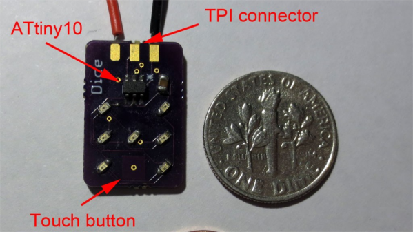
[Tim]’s Dice10 is an exercise in minimalism. Building an electronic dice using an ATtiny10 with code that fits within 1kB is not too difficult. Charlieplexing the LED’s would have used three of the four available GPIO pins. [Tim] upped the game by using just two GPIO pins to drive the seven LED’s for the dice. A third GPIO is used as a touch button input. Besides the ATtiny and the LED’s, the only other component used is a capacitor across the supply inputs.
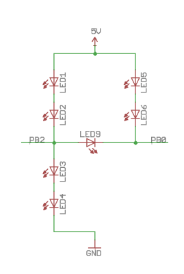
The LED’s are grouped in three pairs of two LED’s and a single centre LED. Usually, Charlieplexed LED’s are connected across pairs of GPIO pins. But his scheme includes connections to the 5V and GND terminals, besides the two GPIO pins. Building a truth table makes it easy to figure out what’s going on.
STATE PB2 PB0 LED's
1     Z   Z   --
2     L   Z   LED 1/2
3     H   Z   LED 3/4
4     Z   L   LED 5/6
5     Z   H   --
6     H   L   LED9
7     L   H   --
8     H   H   --
9     L   L   --
Only the logic states used are listed in the table. It’s possible to add two more LED’s between PB0 and GND and one more anti-parallel with LED9, making a total of 10 LED’s driven by two pins. That’s quite a hack. The important thing here is to have two LED’s in series in the arms that connect to either 5V or GND.
[Tim] has posted the code and hardware source files on his Github repo, and his blog post has some additional details on how he solved the problem.
If you’re looking for more inspirations on minimal dice designs, check this “PIC powered pair of electronic dice” which uses a PIC 12F629 with five outputs driving a pair of 7 pips to make a dual dice.

If you have a cool project in mind, there is still plenty of time to enter the 1 kB Challenge! Deadline is January 5, so check it out and fire up your assemblers!

