Stacking Voltage References To High Voltage Extremes

As children, we all probably had our ideal career paths. As an adult do you still harbor a secret desire to be an astronaut, or to drive a railroad train? Or have holders of other jobs become the people you envy?

As a Hackaday writer it’s probably not too controversial to admit a sneaking envy for the writers of semiconductor application notes. True, often their work consists of dry demonstrations of conventional uses for the products in question, but every once in a while they produce something off the wall and outside the device’s intended use, so out of the ordinary that you envy them their access for experimentation to the resources of a large semiconductor company.

Take Texas Instruments’ Application Report SBAA203, from May 2013. “Stacking the REF50xx for High-Voltage References” (PDF). A laboratory specialising in accurate measurement of high voltages had the problem that the stacks of Zener or avalanche diodes they were using as voltage references lacked both precision and stability, so investigated the properties of the REF5010 10V precision voltage reference.

You'll never be satisfied with a mere Zener diode again.
You’ll never be satisfied with a mere Zener diode again.

They found that by ignoring the device’s data sheet and directly connecting its output pin to its power pin, the REF5010 became equivalent to an ideal Zener diode. In this mode multiple references could be stacked in the same way as a real Zener diode, and very stable and high-precision voltage references could be created with very high voltages. They made a PCB with ten stacked REF5010s for a 100V reference, and then stacked ten of them for a 1000V reference. Leaving it for 24 hours to settle, they achieved a precision of +/- 2.5ppm, and after 3.5 months their average reading for the ten 1000V references they built was 1000.022V.

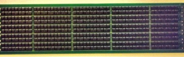
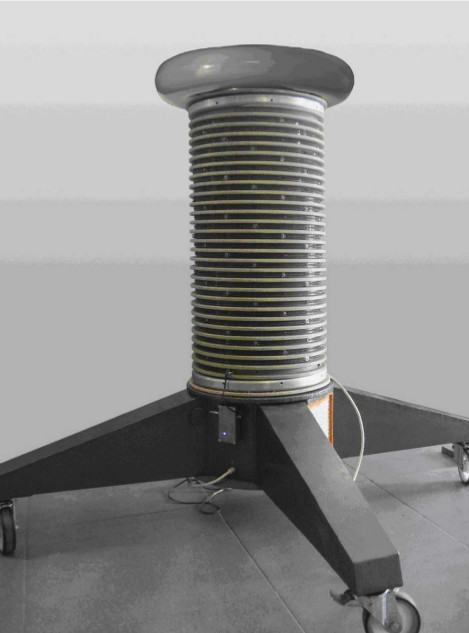
The 1000V reference would be impressive enough, but they weren’t finished. They built a series of boards holding 500 REF5010s for a 5KV reference, and stacked 20 of them to make a 100KV reference. These boards were mounted in a tower looking not unlike the Tesla coils we sometimes feature here. They note that it probably hits the record of simultaneous use of TI parts in a single device.

This may well be the first extremely high voltage precision reference to feature here at Hackaday, but we’ve certainly had our share of HV articles. Earlier this year we had a trio from [Steven Dufresne]: A conucopia of high voltage sources looking at ways to make your EHT, High voltage please, but don’t forget the current looking at selecting the right HV power supply for an application, and Wrangling high voltage looking at construction techniques.

Thanks [Nathan] for the tip.

Everything You’ll Find At The SuperConference

The 2016 Hackaday SuperConference is the ultimate hardware con. It will take place on November 5+6, 2016 in Pasadena, California. SuperCon is about hardware creation — everything at this conference is geared toward sharing the knowledge, excitement, experience, and motivations that go into building cutting edge electronics.

We offer you 48 hours packed with 21 talks, 5 workshops, lightning talks, 4 meals, the Hackaday Prize party, a hardware badge hacking competition, a crypto challenge, and a most excellent village of hackers to enjoy it with. For one weekend Pasadena will be the hardware center of the universe. Get your ticket to the Hackaday SuperConference now.

Want to know more? The full list of talks, works, and details about everything else is found below. We do anticipate adding to this massive list of talks and workshops as we receive final confirmation from the presenters not yet listed.

Continue reading “Everything You’ll Find At The SuperConference”

The Fastest Rise Time In The West: Making A Truly Quick Pulse Edge

When we are taught about oscillators as newbie engineers, we are shown a variety of waveforms on an oscilloscope or in a textbook. This is a sine wave, they say, this is a sawtooth, this is a square wave, and so on. We’re taught to look at the lines on the screen as idealised, a square wave is truly square, and the transition from low to high voltage and back again is instantaneous.

In most cases this assumption is harmless. If we look into the subject a little deeper we learn that what seemed an instantaneous cliff-face is in fact a very steep slope, but when a circuit does its business in milliseconds there is usually no harm in ignoring a transition time measured in nanoseconds. The glue logic for your Arduino project can take its time.

Sometimes though, the rise time of a logic transition is important. The application that prompted this article was the measurement of oscilloscope bandwidth by looking at how quickly the ‘scope catches up with a pulse that exceeds its bandwidth, for example. When the instrument can happily measure the transition times of all your usual  pulse generators, something out of the ordinary is called for. So it’s worth taking a look at the rise times you’d expect from everyday circuitry, examining a few techniques for generating rise times that are much faster.
Continue reading “The Fastest Rise Time In The West: Making A Truly Quick Pulse Edge”

Maker Faire Multicolor And Multi Material 3D Printing

The next frontier of desktop 3D printing is multi-material and multi-color prints. Right now, you can buy a dual toolhead for a Lulzbot, and dual toolheads from other companies exist, although they are a bit rare. In the next few years, we’re going to see a lot of printers able to print dissolvable supports and full-color 3D printers.

Printing in more than one color is almost here, but that doesn’t mean we’re on the cusp of a complete revolution. Multi-material printing is lagging a little bit behind; you’ll be able to print two colors of PLA next year, but printing an object in PLA and ABS is going to be a bit tricky. Printing something in PLA and nylon will be very hard. Color mixing, likewise, will be tricky. We can do it, the tools are getting there, but think of this year as a preview of what we’ll be doing in five years.

Continue reading “Maker Faire Multicolor And Multi Material 3D Printing”

Scanning Parts Into KiCad

You do not know how to make a PCB unless you can make your own parts. [Jan] knows this, but like everyone else he checked out the usual online sources for a footprint for an SD card socket before making his own. It turns out, this SD card socket bought from an online marketplace was completely undocumented. Not only was an Eagle or KiCad footprint unavailable, but CAD files showing the dimensions of the part were non-existent. A solution had to be devised.

Instead of taking calipers and finely measuring all the pads on this SD card socket – a process that would surely fail – [Jan] decided to use a flatbed scanner to trace out the part. The part was placed on the glass and scanned at 300 dpi with a convenient reference object (a public transport card) in the same picture. This picture was imported into a CAD package, scaled to the correct ratio, and exported as a DXF. Since KiCad readily accepts importing DXFs, the CAD file was easily accessed, traced over, and a new part created.

From start to finish, making the footprint for this no-name, off-brand SD card socket took fifteen minutes. That’s nothing compared to the time it would take to manually measure each of the pads, draw a footprint, and print out the footprint at 1:1 scale to see if it matched up several times. It’s awesome work, and a great reminder that the best tools are usually right in front of you.

Hackaday Prize Entry: FPGAs For The Raspberry Pi Zero

The Raspberry Pi is the Arduino of 2016, and that means shields, hats, add-ons, and other fun toys that can be plugged right into the GPIO pins of a Pi. For this year’s Hackaday Prize, [Valentin] is combining the Pi with the next age of homebrew computation. He’s developed the Flea Ohm, an FPGA backpack or hat for the Pi Zero.

The Flea Ohm is based on Lattice’s ECP5 FPGA featuring 24k LUTs and 112kB BRAM. That’s enough for some relatively interesting applications, but the real fun comes from the added 32MB or 128MB of SDRAM, a micro SD card slot, USB + PS/2 host port and an LVDS output.

The combination of Raspberry Pis and FPGAs are extremely interesting and seem to be one of the best FPGA learning platforms anyone can imagine. Another Hackaday Prize entry, the ZinqBerry does a similar trick, but instead of a Pi hat, the ZinqBerry drops a Xilinx Zynq with an FPGA and ARM Cortex A9 core onto a board with Ethernet, HDMI, and USB.

If it’s a Flea or a Zinq, the age of FPGA’d Raspberry Pis is quickly approaching, and hopefully we’ll see them as finalists in the Hackaday Prize. You can check out a video of the Flea Ohm below.

Continue reading “Hackaday Prize Entry: FPGAs For The Raspberry Pi Zero”

A Desk Lamp Solder Fume Extractor

Those of us who have spent a lifetime building electronic projects have probably breathed more solder smoke than we should. This is not an ideal situation as we’ve probably increased our risk of asthma and other medical conditions as a result.

It has become more common over the years to see fume extraction systems and filters as part of the professional soldering environment, and this trend has also started to appear in the world of the home solderer. As always, where commercial products go the hardware hacker will never be far behind. We’ve seen people producing their own soldering fume filters using computer fans.

A particularly neat example comes via [Engineer of None], who has posted an Instructable and the YouTube video shown below the break for a filter mounted on a desk lamp. A toaster is used to heat a piece of acrylic. The softened plastic is then shaped to fit the contours of the lamp. The lamp’s articulated arm is perfect for placing light and fume extraction exactly where it is needed. It’s not the most complex of hacks, but we’d have one like it on our bench without a second thought. We would probably add an activated carbon filter to ours though.

Continue reading “A Desk Lamp Solder Fume Extractor”