Star Trek Material Science Is Finally Real: Transparent Wood

It’s not transparent aluminum, exactly, but it might be even better: transparent wood. Scientists at the University of Maryland have devised a way to remove all of its coloring, leaving behind an essentially clear piece of wood.

IMG_20160518_110605
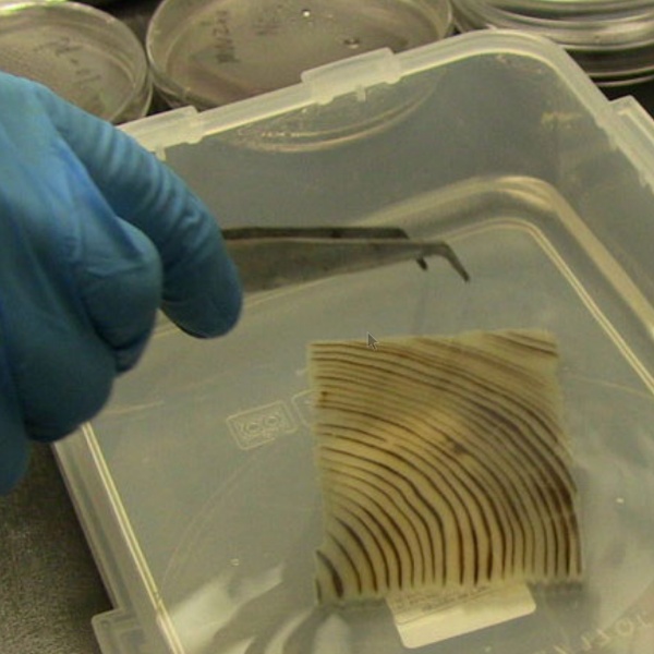
By boiling the block of wood in a NaOH and Na2SO chemical bath for a few hours the wood loses its lignin, which is gives wood its color. The major caveat here is that the lignin also gives wood strength; the colorless cellulose structure that remains is itself very fragile. The solution is to impregnate the transparent wood with an epoxy using about three vacuum cycles, which results in a composite that is stronger than the original wood.

There are some really interesting applications for this material. It does exhibit some haze so it is not as optimally transparent as glass but in cases where light and not vision is the goal — like architectural glass block — this is a winner. Anything traditionally build out of wood for its mechanical properties will be able to add an alpha color channel to the available options.

The next step is finding a way to scale up the process. At this point the process has only been successful on samples up to 1 centimeter thick. If you’re looking to build a starship out of this stuff in the meantime, your best bet is still transparent aluminum. We do still wonder if there’s a way to eliminate the need for epoxy, too.

$25 Satellite Tracker Boasts “Usefulness Optional”

[Paul] is very up-front about the realities of his $25 Satellite Tracker, which aims a tape measure yagi antenna at a satellite of choice and keeps it tracking the satellite as it moves overhead. Does it work? Yes! Is it cheap? Of course! Is it useful? Well… did we mention it works and it’s cheap?

When [Paul] found himself wanting to see how cheaply he could make a satellite tracker he already had an RTL-SDR (which we have seen used for satellite communication before) and a yagi antenna made out of a tape measure, but wanted some way to automatically point the antenna at a satellite as it moved across the sky. He also wanted to see just how economically it could be done. Turns out that with some parts from China and code from SatNOGS (open-source satellite tracking network project and winner of the 2014 Hackaday Prize) you have most of what you need! A few modifications were still needed, and [Paul] describes them all in detail.

Satellite Tracker In Parking Lot ThumbnailSo is a $25 Satellite Tracker useful? As [Paul] says, “Probably not.” He explains, “Most people want satellite trackers so that they can put them outside and then control the antenna from inside, which someone probably can’t do with mine unless they live in a really nice place or build a radome. […] Driving somewhere, setting it up correctly (which involves reprogramming the Arduino for every satellite), and then sitting around is pretty much the opposite of useful.”

It might not be the most practical but it works, it’s cool, he learned a lot, and he wrote up the entire process for others to learn from or duplicate. If that’s not useful, we don’t know what is.

Satellite tracking is the focus of some interesting projects. We’ve even seen a project that points out satellite positions by shining a laser into the sky.

Electromagnetic Field’s Badge Hanging In The Balance

Making conference badges is a tough job. Unless you’re sitting on a gold mine, you have to contact a whole bunch of sponsors for help, work the parts that you can get into a coherent design, and do it all on the quick for a large audience. The EMF team is this close to getting it done, but they need some sponsorship for the assembly. If you know anyone, help them out! If they can’t line something up in the next two weeks, they’ll have to pull the plug on the badge entirely.

Electromagnetic Field is a summer-camp hacker convention / festival that takes place in England and is now in its third iteration. As with other big cons, the badge is a good part of the fun.

The 2016 EMF badge looks to be amazing. It’s powered by an ST STM32L4 low-power micro, a color LCD screen, a TI CC3100 WiFi radio module onboard, and a ridiculous number of other features including a gyro and magnetometer, and a giant battery. It’s also a testbed for the brand-new MicroPython, which aims to bring everyone’s favorite scripting language to embedded processors. In fact, they’ve largely built the MicroPython WiFi drivers for the badge.

If they can’t get a sponsor, all is not lost because everything is open source. We’ll all reap the benefits of their hard work. But that’s not the point. The point is that hundreds of hackers will be standing around in a field outside of London without the most audacious badge that we’ve seen designed dangling from their necks.
If you know anyone who can help, get in touch?

Thanks [schneider] for the tip!

I2c Relay Expander Uses Nifty Card-Edge Connection

[Andrew Sowa] wanted to use an off-the-shelf relay board from Numato Labs. The board lacks a suitable computer interface, which meant that [Andrew] would have to build one, and its input connectors are screw terminals, which meant a lot of wiring. Undeterred, he created an i2c expansion board using an MCP23017 I/O port expander, and with a novel card-edge designed to mate with the screw terminals, solving both problems at once.
Continue reading “I2c Relay Expander Uses Nifty Card-Edge Connection”

Subsea ROV Has 6 Degrees Of Freedom + Autopilot

This is what happens when you give Norwegian engineering students half a year to develop an ROV for their class.

The team utilized 3D printing to design and print their own thruster propellers and ducts for the ROV. It’s powered by HobbyKing motors with VESC speed controllers. This allows them to get from 0.6 to 30N of thrust from each propeller at 12V. Because of this accuracy they’re able to use a PID system to do automatic pitch, roll and depth control!

The electronics are housed in a 200mm acrylic tube (15mm wall thickness) with aluminum end caps and o-rings — an exact pressure rating is not given, but the team could flood the chamber with non-conductive oil to increase that even more — they just don’t need to for tests in a swimming pool. The undersea wire connectors they use (Subconn) are rated for 700 and 600 bar!

Continue reading “Subsea ROV Has 6 Degrees Of Freedom + Autopilot”

Navid Gornall Eats His Own Face

Navid Gornall is a creative technologist at a London advertising agency, which means that he gets to play with cool toys and make movies. That also means that he spends his every working hour trying to explain tech to non-technical audiences. Which is why he was so clearly happy to give a talk to the audience of hardware nerds at the Hackaday Belgrade conference.

After a whirlwind pastiche of the projects he’s been working on for the last year and a half, with tantalizing views of delta printers, dancing-flame grills, and strange juxtapositions of heat sinks and food products, he got down to details. What followed was half tech show-and-tell, and half peering behind the curtain at the naked advertising industry. You can read our writeup of the highlights after the video below.

Continue reading “Navid Gornall Eats His Own Face”

Flying With Proportional – Integral – Derivative Control

Your quad-copter is hovering nicely 100 feet north of you, its camera pointed exactly on target. The hover is doing so well all the RC transmitter controls are in the neutral position. The wind picks up a bit and now the ‘copter is 110 feet north. You adjust its position with your control stick but as you do the wind dies and you overshoot the correction. Another gust pushed it away from target in more than one direction as frustration passes your lips: ARGGGHH!! You promise yourself to get a new flight computer with position hold capability.

How do multicopters with smart controllers hold their position? They use a technique called Proportional – Integral – Derivative (PID) control. It’s a concept found in control systems of just about everything imaginable. To use PID your copter needs sensors that measure the current position and movement.

The typical sensors used for position control are a GPS receiver and an Inertial Management  Measurement Unit (IMU) made up of an accelerometer, a gyroscope, and possibly a magnetometer (compass). Altitude control would require a barometer or some other means of measuring height above ground. Using sensor fusion techniques to combine the raw data, a computer can determine the position, movement, and altitude of the multicopter. But calculating corrections that will be just right, without over or undershooting the goal, is where PID comes into play. Continue reading “Flying With Proportional – Integral – Derivative Control”