Even with Amazon’s Echo Show devices running Linux in the form of the Android-derived FireOS, using them for non-Amazon approved purposes can be a chore at best. In the case of the Echo Show 8 even simple workarounds using ADB and the bootloader have been locked-down, requiring more drastic measures. Here [Vowed] over at the XDA forums shows off one such hack, involving directly tapping into the device’s eMMC.
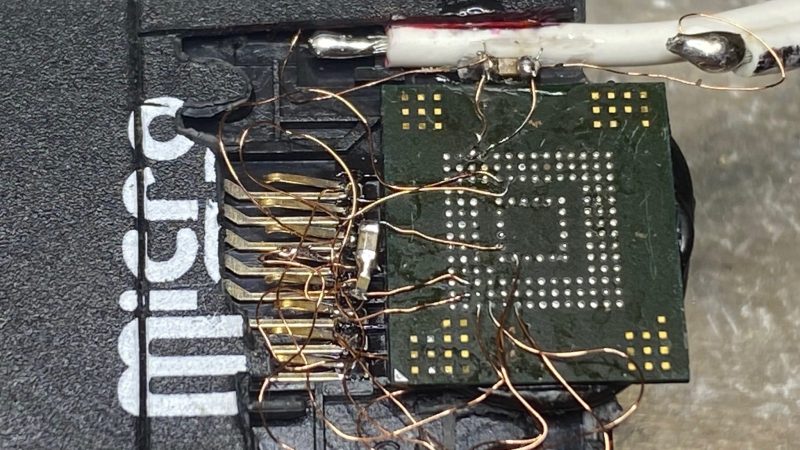
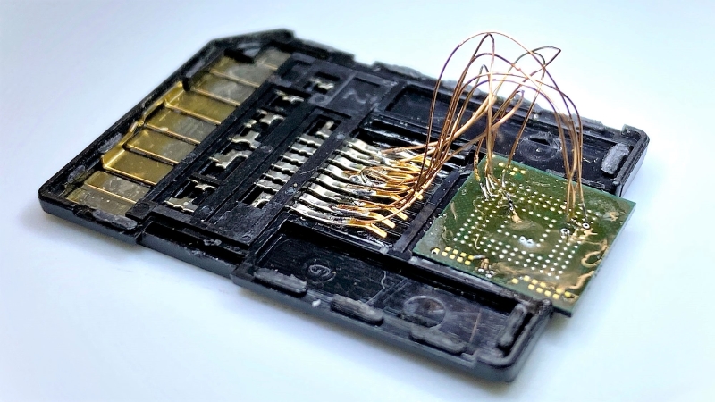
Suffice it to say that this is not a hack for the faint of heart, with even the iFixit teardown guide for this device being rather daunting. Even after you get access to the mainboard, you still have to remove or cut open the metal can that covers the eMMC, so that you can unleash an eMMC programmer on it. It’s best to make sure to make a backup image of the original contents too, just in case you have to restore things.
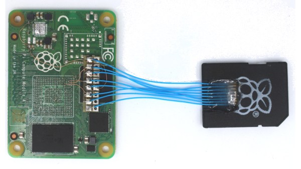
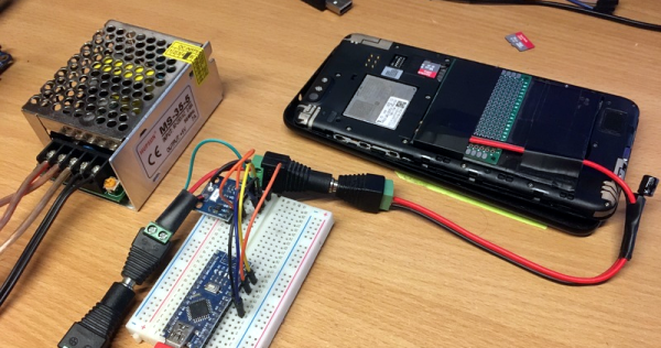
With the shield out of the way you can solder fine wires to pads that connect to the eMMC to program it. You also have to solder wires to pads for the UART, though if you’re fancy you can also create a custom pogo pin adapter. With a serial connection established to the original firmware you can then enable features like ADB, and courtesy of the connected eMMC adapter it’s possible to directly alter system files to make rooting as easy as possible.
In addition to rooting the system you can also do a straight replacement of the eMMC contents, such as the demonstrated Debian installation. Even if not the most easy of mods, it’s good to see that it’s possible to repurpose these devices.
(Top image: Amazon Echo Show 8 3rd generation mainboard. Credit: iFixit, CC BY-NC-SA 3.0.)