Things seem to go in cycles. Writing a document using old-fashioned tools like TROFF or LaTeX is like knowing a secret code. Visual editors quickly took over, although even WordStar had some “dot commands” that you put in as text. Then HTML showed up and we were back to coding formatting as text strings.
Fast forward to the present, and HTML’s ubiquity makes that seem normal. Sure, there are visual editors, but it seems perfectly normal now to write <b> for bold text. However, as HTML grows to handle more tasks it also gets more complex. That’s led to the creation of things like Markdown which is just for simple text formatting. Continue reading “Documentation By Markup”→
KiCad is the premiere open source electronics design automation suite. It’s used by professionals and amateurs alike to design circuits and layout out printed circuit boards. In recent years we’ve seen some incredible features added to KiCad like an improved 3D viewer and push-and-shove routing. This Friday at 10 am PST, join in a Hack Chat with KiCad lead developer [Wayne Stambaugh] to talk about recent improvements and what the team has planned for KiCad in the future.
[Wayne] has been an electronics engineer for over 30 years with a wide range of experience in analog and digital hardware design and embedded and application software design. He started hacking on KiCad ten years ago when the project was first opened to public development and a little over two years ago became the project leader. This is an excellent opportunity to learn how the development team works, what their current goals are, and to talk all things KiCad.
Also on Friday, taking place just an hour before the KiCad chat, is a Tindie Hack Chat. All are welcome as the 9:00 am PST discussion gets under way. Discussion will focus on all aspects of selling unique hardware on Tindie.
Here’s How to Take Part:
Buttons to join the project and enter Hack Chat
Hack Chat are live community events that take place in the Hackaday.io Hack Chat group messaging. Visit that page (make sure you are logged in) and look for the “Join this Project Button” in the upper right. Once you are part of the project, that button will change to “Team Messaging” which takes you to the Hack Chat.
You don’t have to wait for Friday, join Hack Chat whenever you like and see what the community is currently talking about.
Join Us Next Week Too for CircuitPython
Block out your calendar for noon PST on Friday the 27th for next week’s Hack Chat. Joining us are Adafruit’s Ladyada, Tony DiCola, and Scott Shawcoft. They’ll be leading a discussion about CircuitPython Beta, Adafruits new extension to MicroPython that adds SAMD21 support and other enhancements.
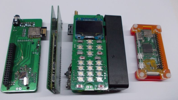
There are several open source phones out there these days, but all of them have a downside. Hard to obtain parts, hard to solder, or difficult programming systems abound. [Arsenijs] is looking to change all that with ZeroPhone. ZeroPhone is based upon the popular Raspberry Pi Zero. The $5 price tag of the CPU module means that you can build this entire phone for around $50 USD.
The radio module in the ZeroPhone is the well known SIM800L 2G module. 2G is going away or gone in many places, so [Arsenijs] is already researching more modern devices. An ESP8266 serves as the WiFi module with an OLED screen and code in python round out this phone. Sure, it’s not a fancy graphical touchscreen, but a full desktop is just a matter of connecting a display, mouse, and keyboard.
For the security conscious, the ZeroPhone provides a unique level of control. Since this is a Raspberry Pi running Linux, you choose which modules are included in the kernel, and which software is loaded in the filesystem. And with news that we may soon have a blobless Pi, the firmware hiding in the radio modules are the only black boxes still remaining.
There was a time when Radio Shack offered an incredible variety of supplies for the electronics hobbyist. In the back of each store, past the displays of Realistic 8-track players, Minimus-7 speakers, Patrolman scanners, and just beyond the battery bin where you could cash in your “Battery of the Month Club” card for a fresh, free 9-volt battery, lay the holy of holies — the parts. Perfboard panels on hinges held pegs with cards of resistors for 49 cents, blister packs of 2N2222 transistors and electrolytic capacitors, and everything else you needed to get your project going. It was a treasure trove to a budding hardware hobbyist.
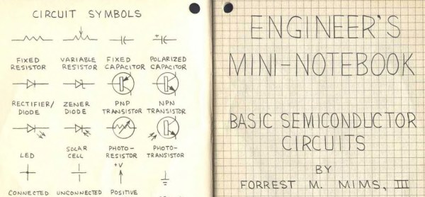
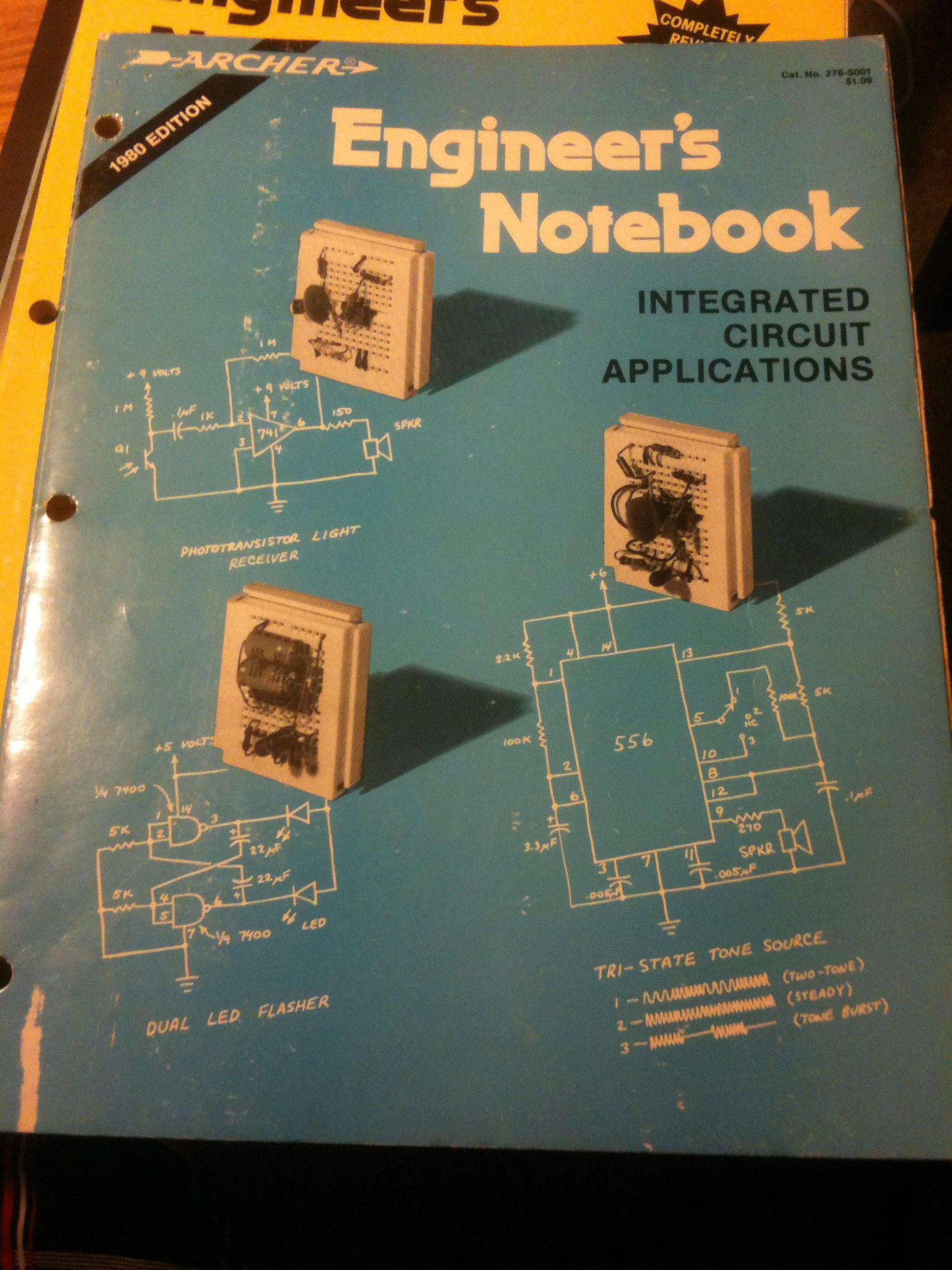
But over on the side, invariably near the parts, was a rack of books for sale, mostly under the Archer brand. 12-year old me only had Christmas and birthday money to spend, and what I could beg from my parents, so I tended to buy books — I figured I needed to learn before I started blowing money on parts. And like many of that vintage, one of the first books I picked up was the Engineer’s Notebook by Forrest M. Mims III.
Wish I could find my original copy from 1979. I just bought this one from Amazon.
Many years rolled by, and my trusty and shop-worn first edition of Mims’ book, with my marginal notes and more than one soldering iron burn scarring its pulp pages, has long since gone missing. I learned so much from that book, and as I used it to plan my Next Big Project I’d often wonder how the book came about. Those of you that have seen the book and any of its sequels, like the Mini-notebook Series, will no doubt remember the style of the book. Printed on subdued graph paper with simple line drawings and schematics, the accompanying text did not appear to be typeset, but rather hand lettered. Each page was a work of technical beauty that served as an inspiration as I filled my own graph-paper notebooks with page after page of circuits I would find neither the time nor money to build.
I always wondered about those books and how they came about. It was a pretty astute marketing decision by Radio Shack to publish them and feature them so prominently near the parts — sort of makes the string of poor business decisions that led to the greatly diminished “RadioShack” stores of today all the more puzzling. Luckily, Forrest Mims recently did an AMA on reddit, and he answered a lot of questions regarding how these books came about. The full AMA is worth a read, but here’s the short story of those classics of pulp non-fiction.
Every time we say “We’ve seen it all”, along comes a project that knocks us off. 60 year old [Mark Nesselhaus] likes to learn new things and he’s never worked with hardware at the gate level. So he’s building himself a 4-bit Computer, using only Diode-Transistor Logic. He’s assembling the whole thing on “card board” perf-board, with brass tacks for pads. Why — because he’s a thrifty guy who wants to use what he has lying around. Obviously, he’s got an endless supply of cardboard, tacks and Patience. The story sounds familiar. It started out as a simple 4-bit full adder project and then things got out of hand. You know he’s old school when he calls his multimeter an “analog VOM”!
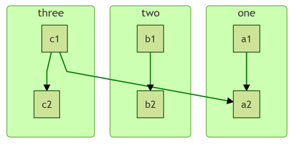
It’s still work in progress, but he’s made a lot of it in the past year. [Mark] started off by emulating the 4-bit full adder featured on Simon Inns’ Waiting for Friday blog. This is the ALU around which the rest of his project is built. With the ALU done, he decided to keep going and next built a 4-to-16 line decoder — check out the thumbnail image to see the rats nest of jumbled wires. Next on his list were several flip flops — R-S, J-K and D types, which would be useful as program counters. This is when he bumped into problems with signal levels, timing and triggering. He decided to allow himself the luxury of adding one IC to his build — a 555 based clock generator. But he still needed some pulse shaping circuitry to make it work consistently.
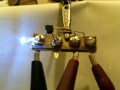
LED Driver : from left, Gnd, NC, +5V, Input
[Mark] also built a finite-state-machine sequencer based on the work done by Rory Mangles TinyTim project. He finished building some multiplexers and demultiplexers, and it appears he may be using a whole bank of 14 wall switches for address, input and control functions. For the output display, he assembled a panel using LED’s recovered from a $1 Christmas light string. Something seems amiss with his LED driver, though — 2mA with LED on and >2.5mA with LED off. The LED appears to be connected across the collector and emitter of the PNP transistor. Chime in with your comments.
This build seems to be shaping along the lines of the Megaprocessor that we’ve swooned over a couple of times in the past. Keep at it, [Mark]!
January, for many of us in the Northern Hemisphere, can be a depressing month. It’s cold or wet depending where you live, the days are still a bit short, and the summer still seems an awfully long way away. You console yourself by booking a ticket to a hacker camp, but the seven months or so you’ll have to wait seems interminable.
If you want an interesting project to look forward to, take a look at [Benadski]’s idea for a decentralised low voltage local DC power grid for the upcoming SHA 2017 hacker camp in the Netherlands. The idea is to create a network that is both safe and open for hacking, allowing those with an interest in personal power generation to both have an available low-voltage power source and share their surplus power with other attendees.
The voltage is quoted as being 42V DC +/- 15%, which keeps it safely under the 50V limit set by the European Low Voltage Directive. Individuals can request a single 4A connection to the system, and villages can have a pair of 16A connections, which should supply enough for most needs. Users will need to provide their own inverters to connect their 5V or 12V appliances, fortunately a market served by numerous modules from your favourite Far Eastern sales portal.
This project will never be the solution to all power distribution needs, but to be fair that is probably not the intention. It does however provide a platform for experimentation, collaboration, and data gathering for those interested in the field, and since it is intended to make an appearance at future hacker camps there should be the opportunity for all that built up expertise to make it better over time.
In most mechanical systems, metal gears that bend are a bad thing. But not so for strain wave gearing, which is designed to take advantage of a metal gear flexing to achieve an action much like planetary gears. The fun isn’t limited to metal anymore, though, if you 3D print a strain wave gear like this.
Strain-wave gearing is nothing new – it was invented in 1957 and has traveled to the moon on the lunar rover. And you may recall [Kristine Panos]’ recent article on a LEGO strain wave gear, which makes it easy to visualize how they work. She also has a great description of how the flex spline, wave generator, and circular spline interact, so we’ll spare those details here. [Simon Merret]’s interpretation of the strain wave gear is very simple and similar to other 3D-printed versions, except that he uses an inside-out timing belt as the flex spline. The wave generator is just an arm with a roller bearing at each end, and despite needing a few tweaks the gear does an admirable job.
Simon is reaching out for help in getting this gear ready for use where the industrial versions see frequent application – the first and second degrees of freedom of robotic arms. If you’ve got any ideas, head over to his project page on Hackaday.io and pitch in.