sample of automatically generated comics

Read Your Movies As Automatically Generated Comic Books

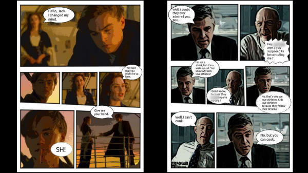
A research paper from Dalian University of Technology in China and City University of Hong Kong (direct PDF link) outlines a system that automatically generates comic books from videos. But how can an algorithm boil down video scenes to appropriately reflect the gravity of the scene in a still image? This impressive feat is accomplished by saving two still images per second, then segments the frames into scenes through analysis of region-of-interest and importance ranking.

movie to comic book pipeline diagram

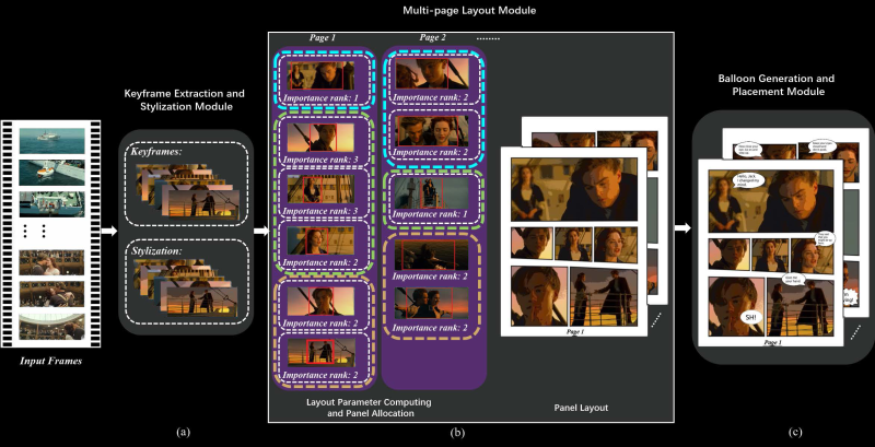
For its next trick, speech for each scene is processed by combining subtitle information with the audio track of the video. The audio is analyzed for emotion to determine the appropriate speech bubble type and size of the subtitle text. Frames are even analyzed to establish which person is speaking for proper placement of the bubbles. It can then create layouts of the keyframes, determining panel sizes for each page based on the region-of-interest analysis.

The process is completed by stylizing the keyframes with flat color through quantization, for that classic cel shading look, and then populating the layouts with each frame and word balloon.

The team conducted a study with 40 users, pitting their results against previous techniques which require more human intervention and still besting them in every measure. Like any great superhero, the team still sees room for improvement. In the future, they would like to improve the accuracy of keyframe selection and propose using a neural network to do so.

Thanks to [Qes] for the tip!

How Laser Headlights Work

When we think about the onward march of automotive technology, headlights aren’t usually the first thing that come to mind. Engines, fuel efficiency, and the switch to electric power are all more front of mind. However, that doesn’t mean there aren’t thousands of engineers around the world working to improve the state of the art in automotive lighting day in, day out.

Sealed beam headlights gave way to more modern designs once regulations loosened up, while bulbs moved from simple halogens to xenon HIDs and, more recently, LEDs. Now, a new technology is on the scene, with lasers!

Continue reading “How Laser Headlights Work”

Cursed USB-C: When Plug Orientation Matters

One of the selling points of the USB-C plug is that supposedly there is no way to incorrectly insert it. As [Pim de Groot] shows with a ‘Cursed USB-C 2.0 Device‘, reality is a bit more complicated when it comes to USB 2.0 compatibility in USB-C. He made a PCB that elegantly demonstrates the simplicity of the problem, featuring two LEDs. Only one orientation of the USB-C plug will cause one of the LEDs to light up green, with the other orientation leaving both LEDs blinking red.

Sigil on the back of the cursed USB-C 2.0 device, by Pim de Groot.

The reason for this behavior is simple: as [Pim] explains, although the USB-C plug has only a single pair of data lines (D+/-) for USB 2.0 connectivity, the receptor duplicates these on either side of its pins, leading out two pairs of D+/- lines. Normally you would connect the matching lines in these pairs together to ensure consistent behavior no matter the plug orientation, but you don’t have to.

By leading each USB 2.0 data pair to its own SAMD11C MCU, only one of the MCUs would be connected to USB, resulting in the connected MCU blinking the LEDs. With a bit more circuitry it’s possible to detect which way around the plug is inserted and use this information in a single MCU system, altering its behavior. While at first glance this seems little more than a fun party trick, but it also offers insight in a possible failure mode of USB-C 2.0 devices where only one plug orientation works, due to broken traces or pads.

Board view of [Pim]’s Cursed USB-C 2.0 Device.

(Heading image: Cursed USB-C 2.0 Device, by Pim de Groot)

Bringing Some Coulter To The Bench: Measuring Tiny Particles With Nanopore Sensing

We’ve all been there: you’re sitting at your bench, with a beaker full of some conductive fluid with a bunch of tiny particles suspended in it, and you want to measure the sizes of each particle.

Okay, maybe this isn’t a shared experience we’ve all had, but It’s at least an ordeal Hackaday alum [Nava Whiteford] has been through, and he was able to carry out the measurements in question using a neat apparatus known as a Coulter counter.

Imagine a container full of a conductive fluid. If you place an electrode at each end, the fluid will carry a current. 
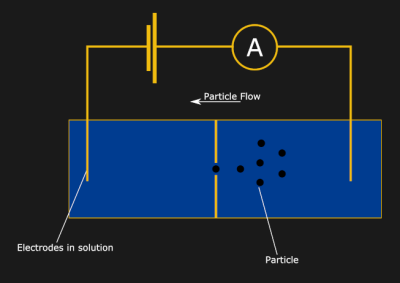
Now, drop an insulating divider in the middle of the container, and the current will stop flowing. Finally, poke a small hole (or nanopore) in the divider. Huzzah! The current is flowing again… but how does this let us measure particle sizes? Well, now think about a tiny particle moving through the hole in the divider. As the particle passes through, the hole will be partially blocked, and the current flow will be partially interrupted. It turns out, the resulting dip in current is proportional to the volume of the particle — a fun property known as the Coulter principle.

[Nava] built a great demo of the system with a macropore in place of the nanopore. The pore in question was a hole melted into a bottle cap, which was suspended in a beaker by two toothpicks. [Nava] used small chips of Acrylic as the particles to be measured, which they pipetted into the solution of KCl. They then passed a current through the solution and used an oscilloscope to sense the interruptions. Be sure to check out their write up for a video of the system in action!

Of course, this technique has a much wider range of applications than measuring little bits of plastic — obtaining blood cell counts, for one. We’ve seen particle counters for use in the air before, but it’s great to see that there’s a way to measure particles in an aqueous solution —  you know, in case we ever find ourselves in such a situation.